Backlight repair Philips 49inch 4k smart-tv

Philips 49PUS6561/12 is the specific model I'm repairing.
Chassis model: QM16.3E
You can use this article as a tutorial. Models that have the same chassis build:
49PUS6401/12
49PUT6401/12
49PUS6401/60
49PUS6501/12
49PUS6501/60
49PUS6551/12
49PUS6561/12
49PUS6581/12
49PUS7101/12
49PUS7101/60
49PUS7181/12
Other models might differ to mutch
Official service manual: direct-download | archive

I'm in no way a professional, I repair devices as a hobby. There are always better ways to repair something.
Join me in my attempt to repair this TV! Anything to add or tips so I can learn? just send a mail to philipstvrepair(at)seppdroid(dot)com
Intro:
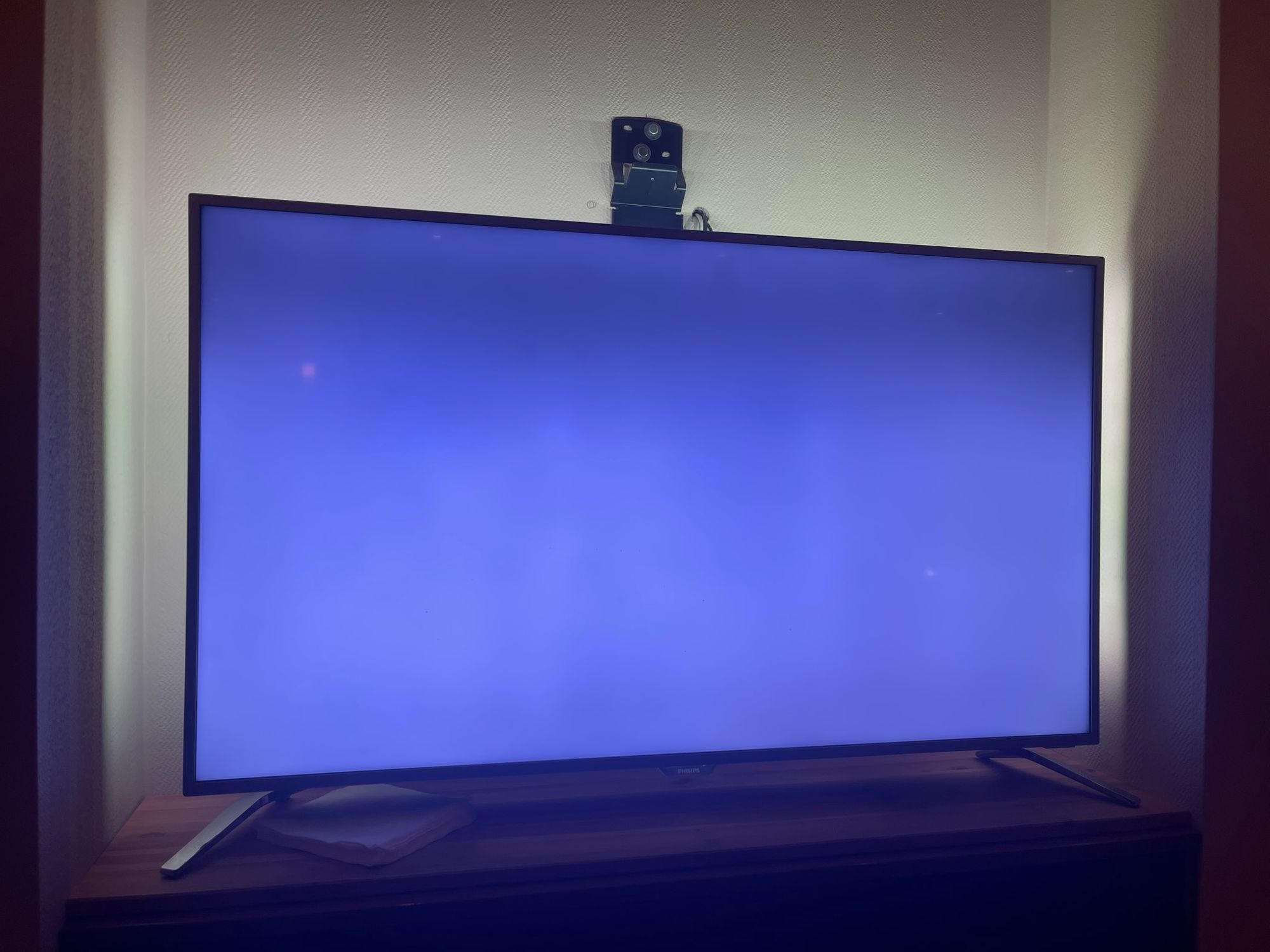
The first symptom I noticed was the dark bar at the top of the screen, I immediately knew that that was a backlight issue. It was annoying, but you could still watch tv.

Last week the whole backlight stopped working... Only the audio was still working. When shining a bright light I could see that the LCD was still displaying images.
(tried to take a picture but that didn't work)
DEMOLI.. I mean disassemble..:
Let's start disassembling the TV.
First, lay it down on its face. (preferably a soft surface)
Always disconnect a device from the mains power if you are disassembling it.
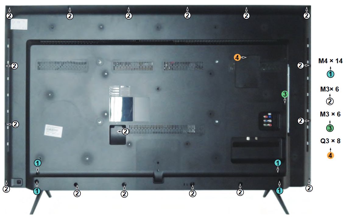
Remove all the screws as shown above.
Then remove the feet, this is different for different models. In my case, I have the wide feet instead of a single base. And I could just pull them out from underneath.
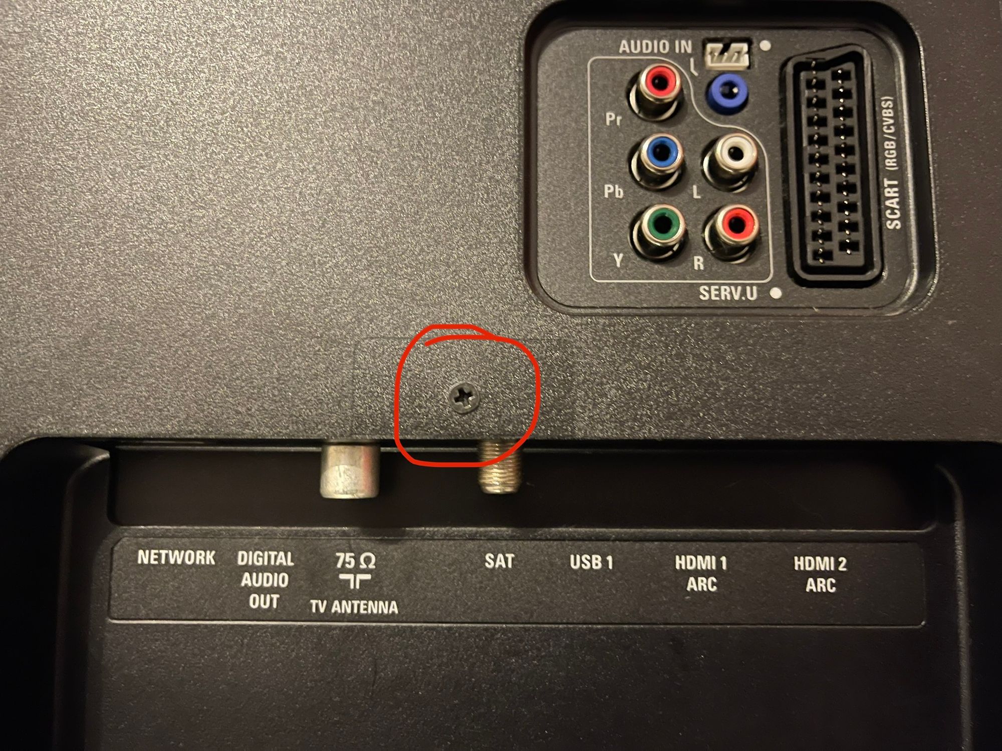
NOTE: My tv had an extra screw, yours might have too. Always check if all screws are removed
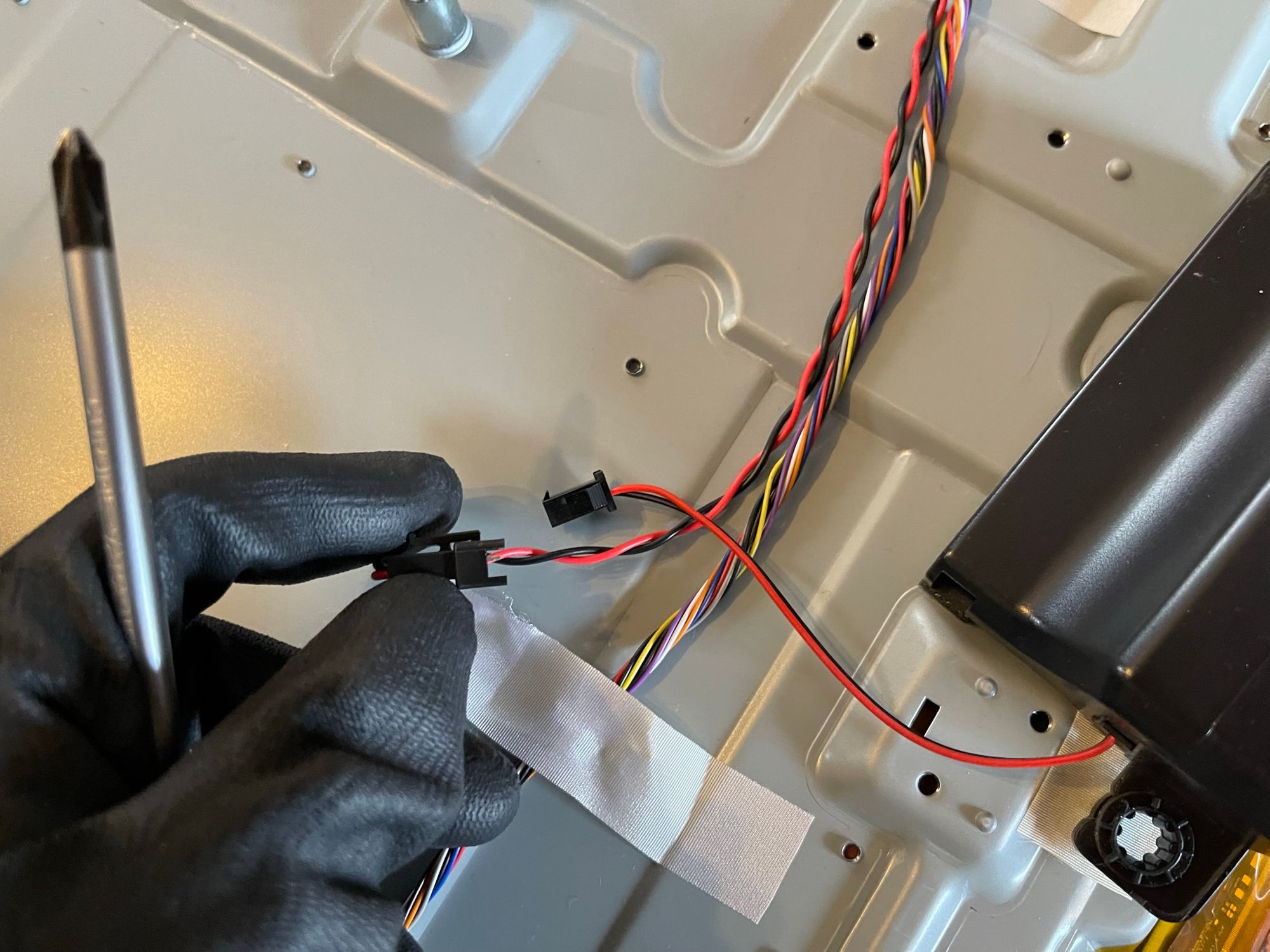
You can open the little service hatch when removing screw-4 and disconnect the Ambilight connector. (if applicable)
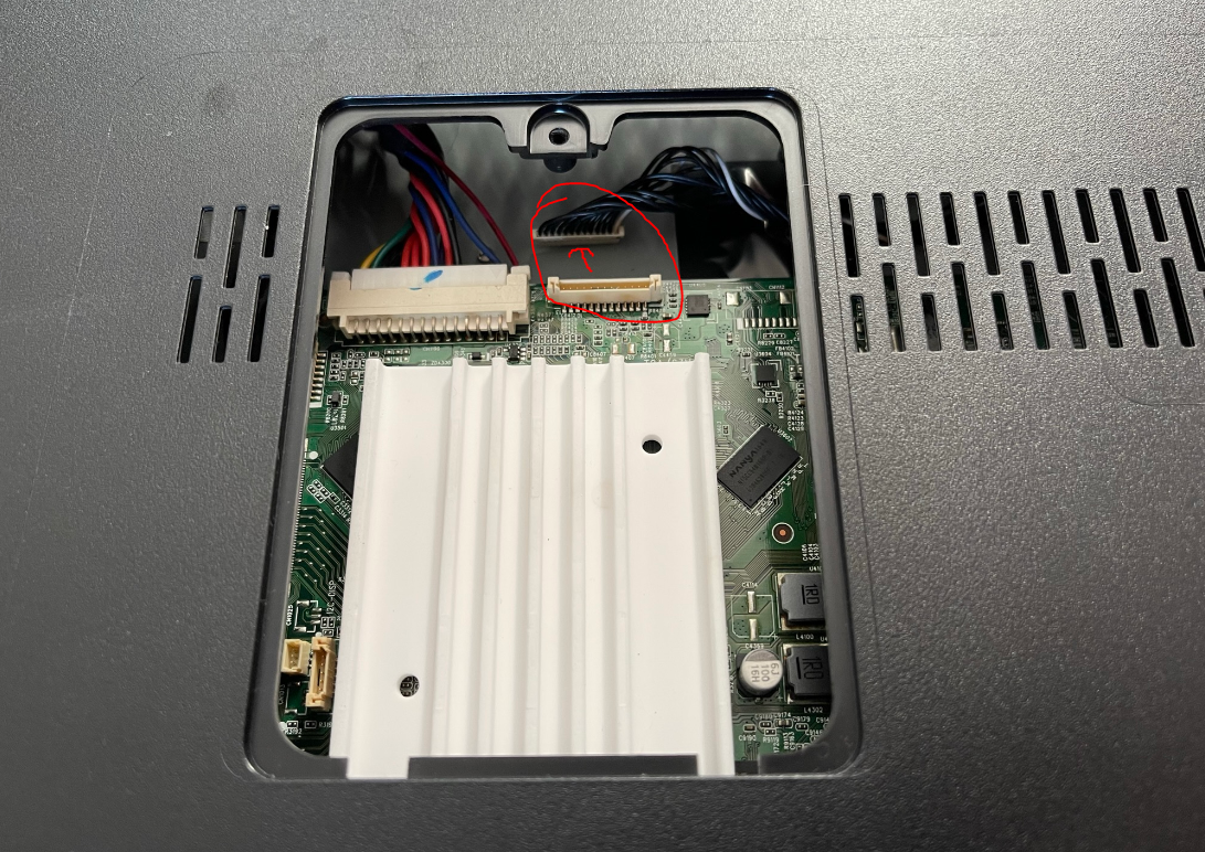
make sure to always try and pull on the connector itself, 9 of the 10 connectors always have some kind of tab to push or pull.
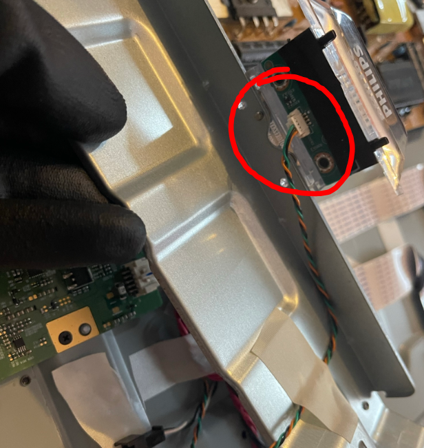
Now we remove the IR sensor. It's the little plastic thing where you also have the status led. Remove the screw and push it up. I had to pull mine a bit before I was able to push it up. Just follow the arrow.
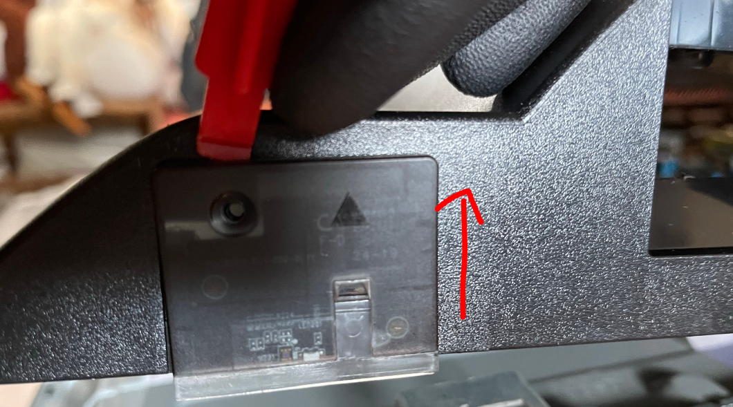
Don't forget to disconnect the cable.
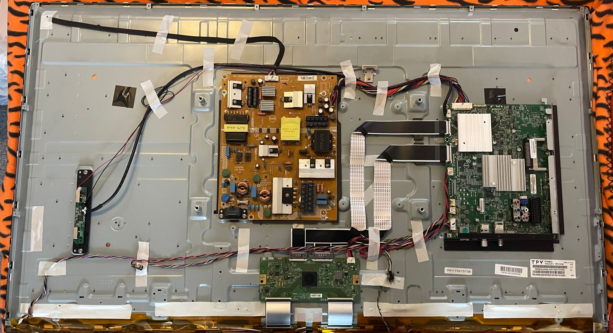
You can now pull off the back plastic cover. I started at the top of the tv as I found that easier.
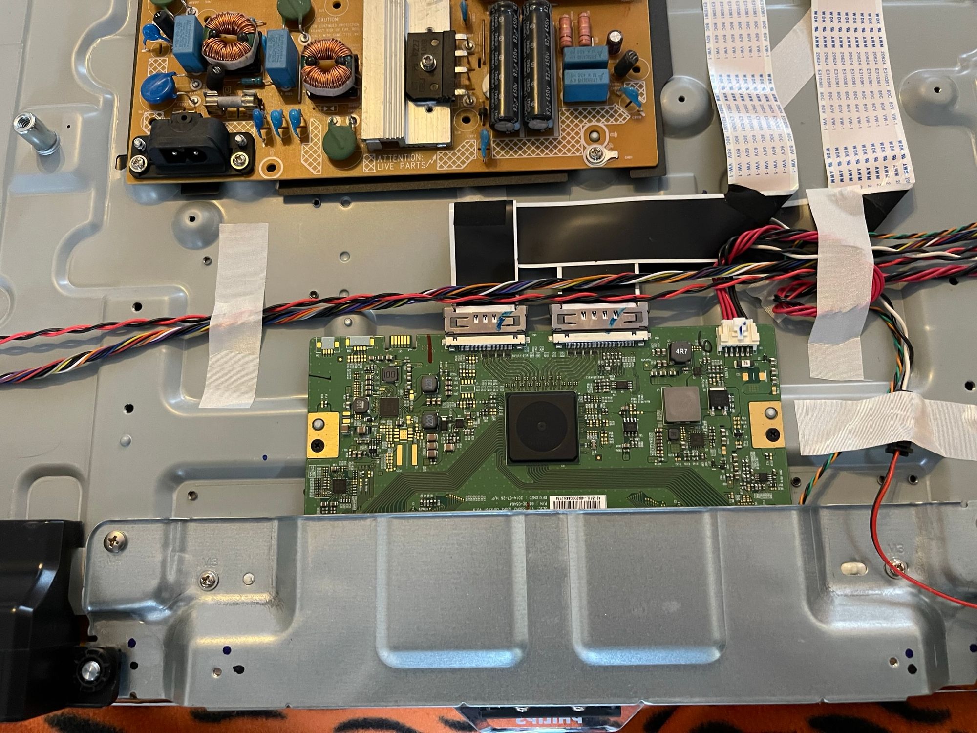
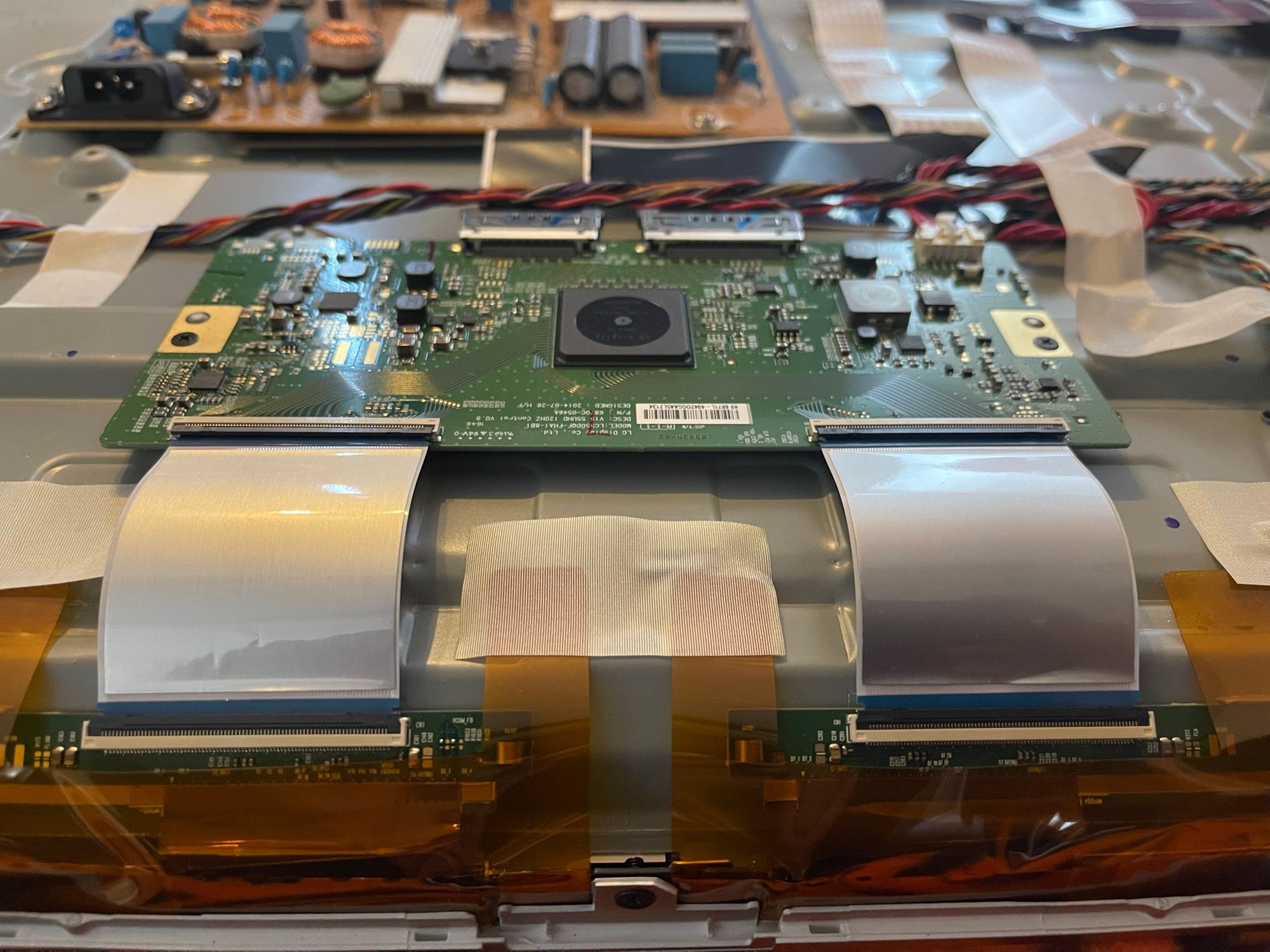
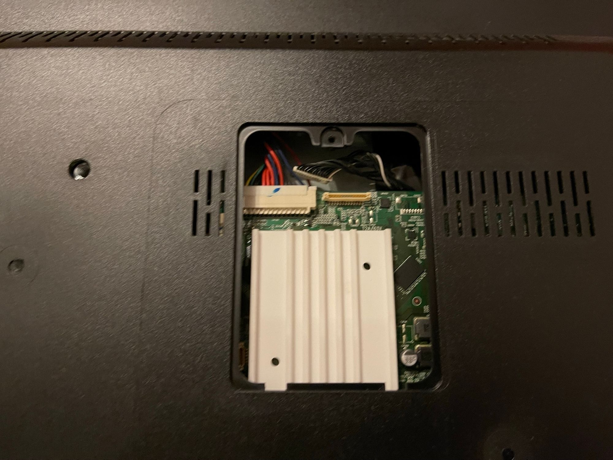
The brownish circuit board in the middle is the PowerSupply
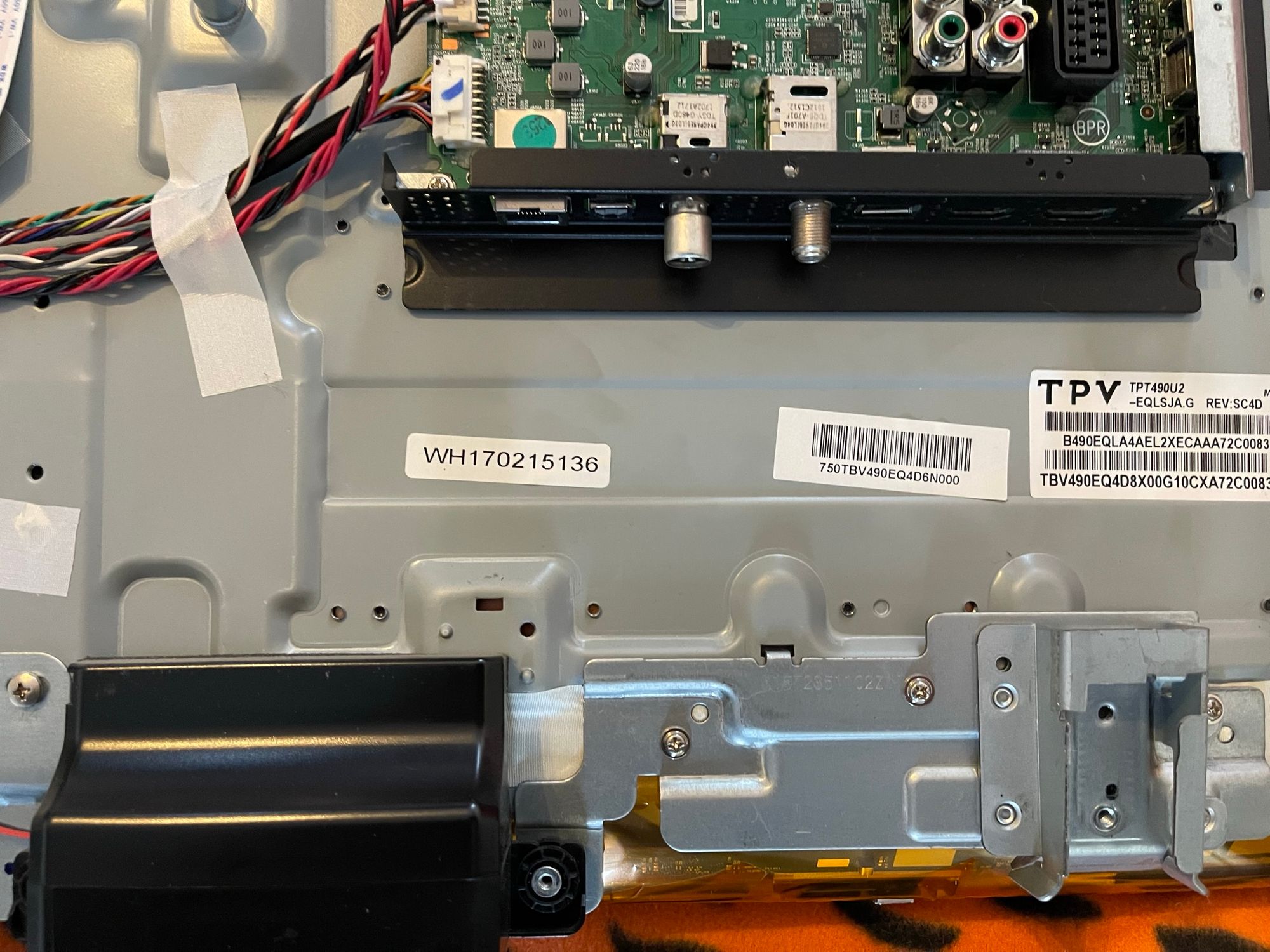
To the right, we have the mainboard, with signalproccesing and (probably) the smart-tv processor.
At the bottom you have the display controller, with the ribbons that go to a break-out board, please watch out! LCD ribbons are known for being weak. 1 rip and its game over.
The PSU looks fine at first sight. No bulging/leaking capacitors. No black dust or burn marks.
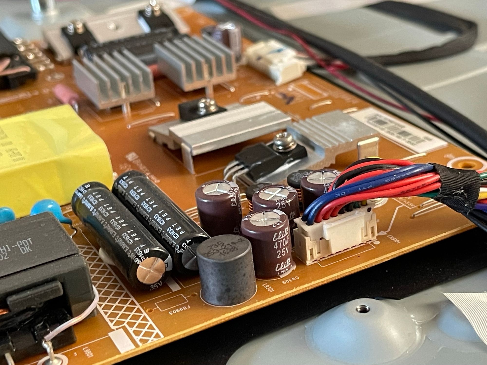
Use your favorite search engine and search "bad capacitors" to know what they look like when they go bad. Sometimes they go bad invisibly, but I didn't feel like testing all the power supply parts. Since I don't consider the PSU as a suspect.
PLEASE don't touch anything on a power supply. High voltage capacitors can injure you.
We are going to do something a bit dangerous, but I need to know before replacing the backlight LEDs that we are getting the right voltage from the power supply. So I'm going to power on the TV and measure the power rail going to the backlight LEDs.
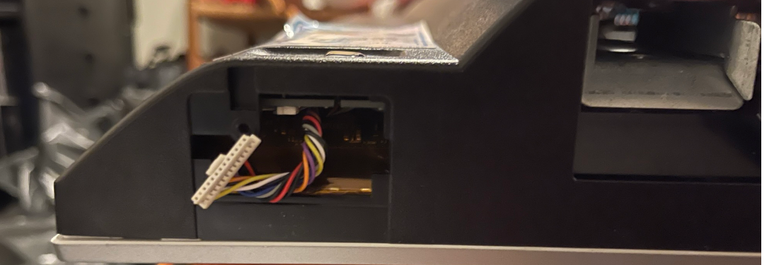
Luckily all the connectors have an information table, so finding the led connector was easy.
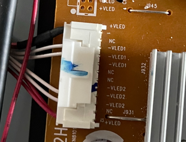
+VLED is power positive and -VLED1/2 is negative.
Now we have to reattach the IR sensor, so we can turn on the TV with the remote.
Now attach the AC power cable to the power supply and plug it into the mains power, The circuits are now fully live. Now you REALLY have to be careful. Any mistakes could fry components or even worse; YOU!
results:
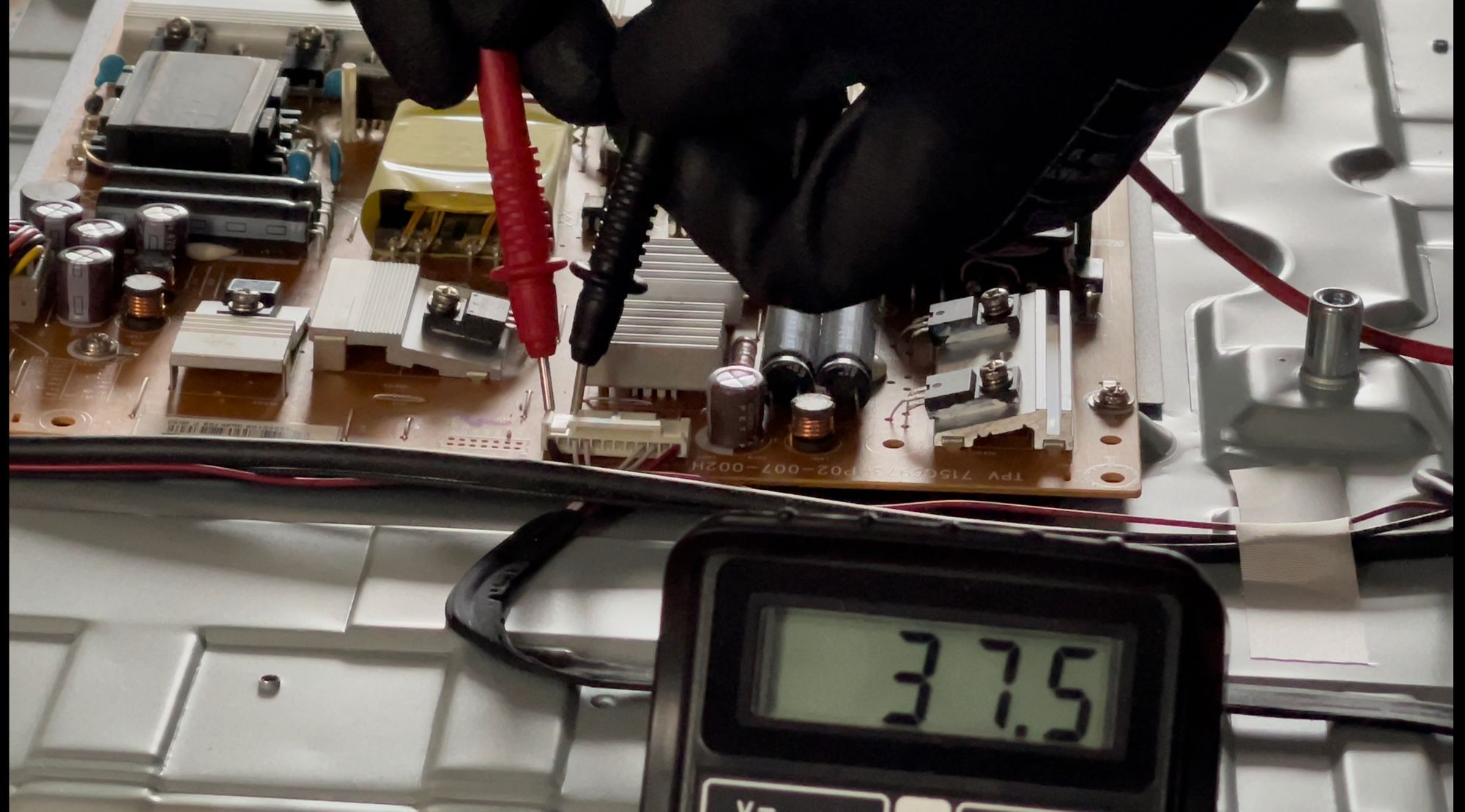
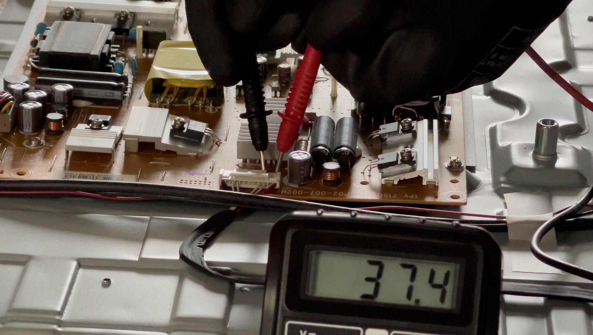
Both positive terminals produce 37,5 volts. Not absurdly high/low. I tried to read the schematic to see what voltage it should produce but it's a too advanced circuit for me. Logically, the voltage has to be variable and not static.
I left that for what it was.
I decided to go further, the led strips cost 30 euros so it's worth the gamble.
Now we need to remove the frame part that also holds the feet:
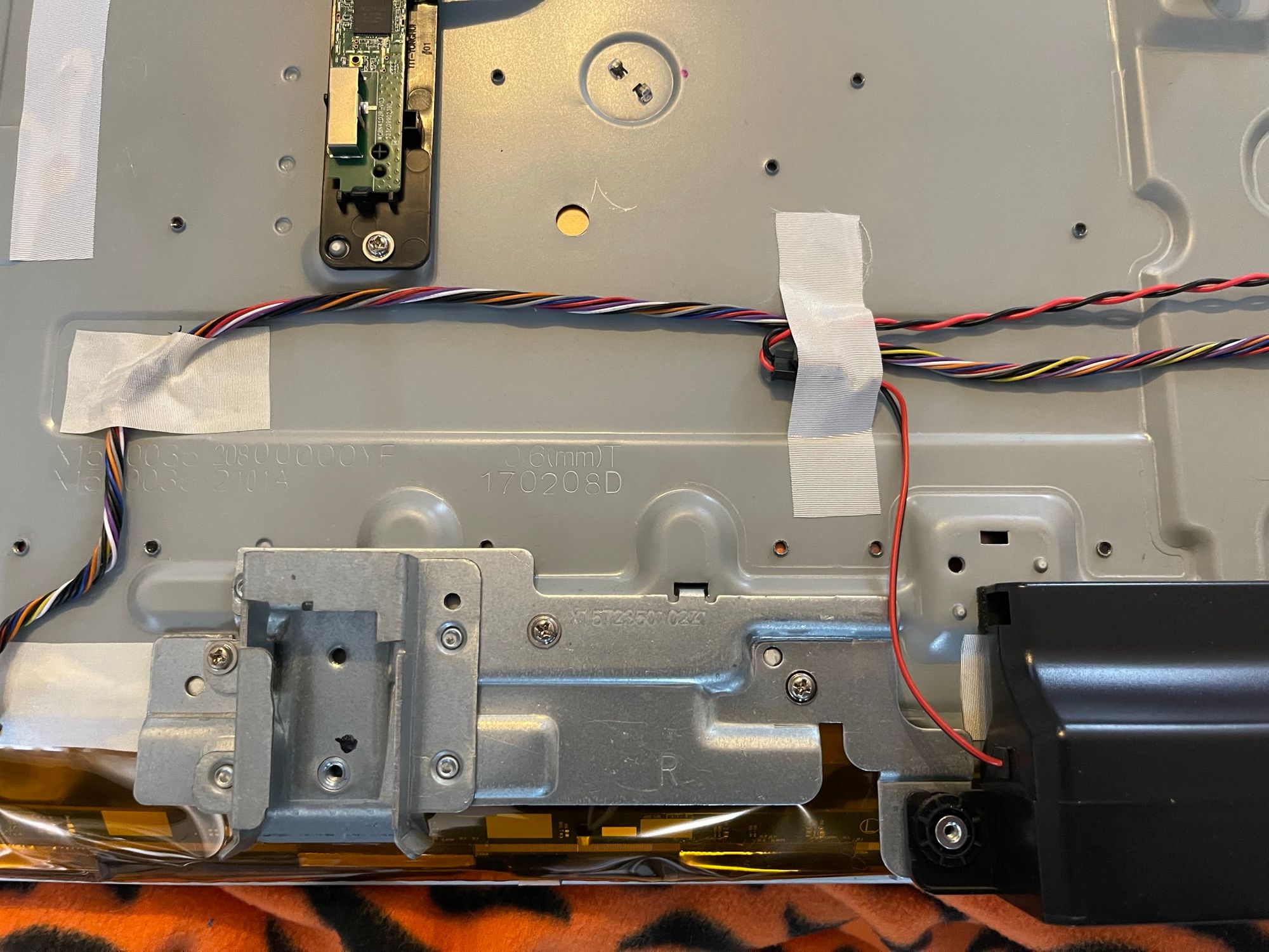
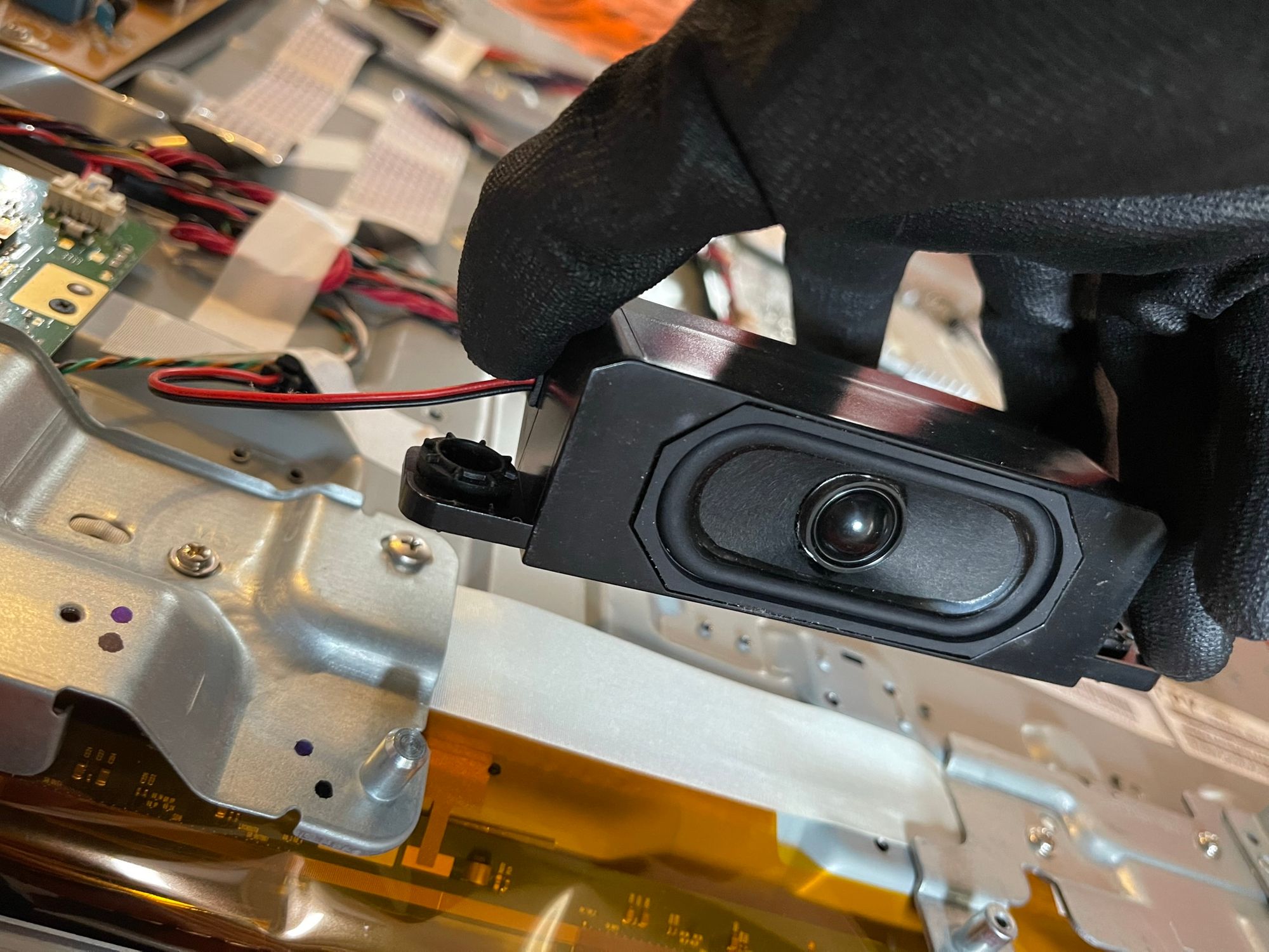
First, disconnect both speakers and pull them up.
Then remove all screws from the bottom frame. It comes apart into 3 parts.
Make sure to disconnect the logo in the middle
Your tv should now look like this:
Now we are slowly heading to the hard part... The LCD connector.
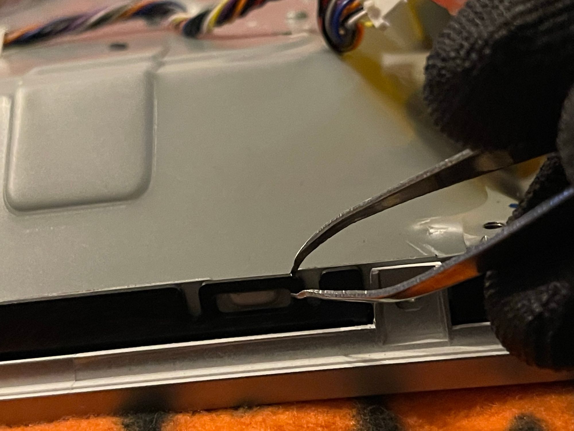
First, disconnect the 2 ribbons by lifting the black connector lever.
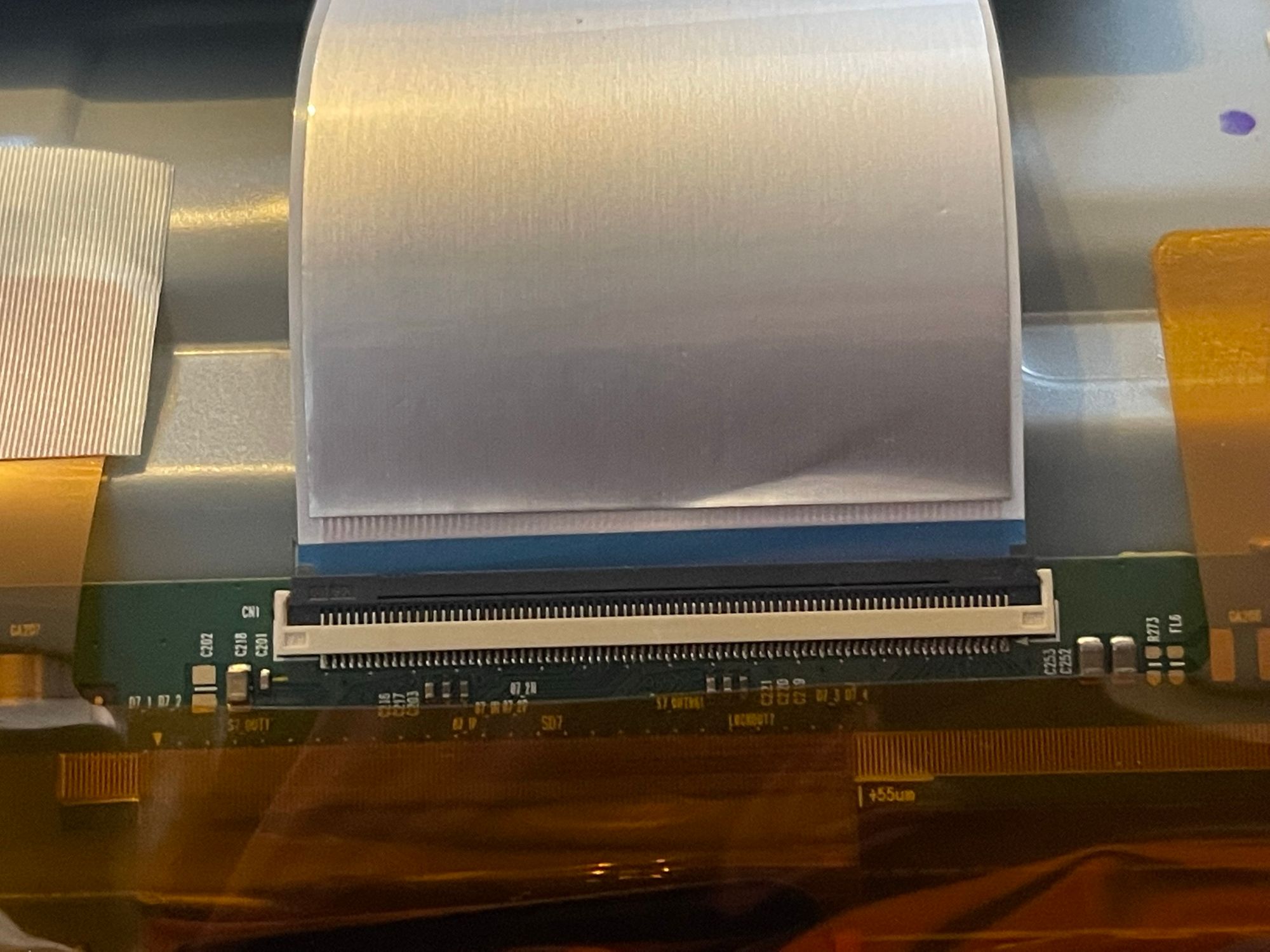
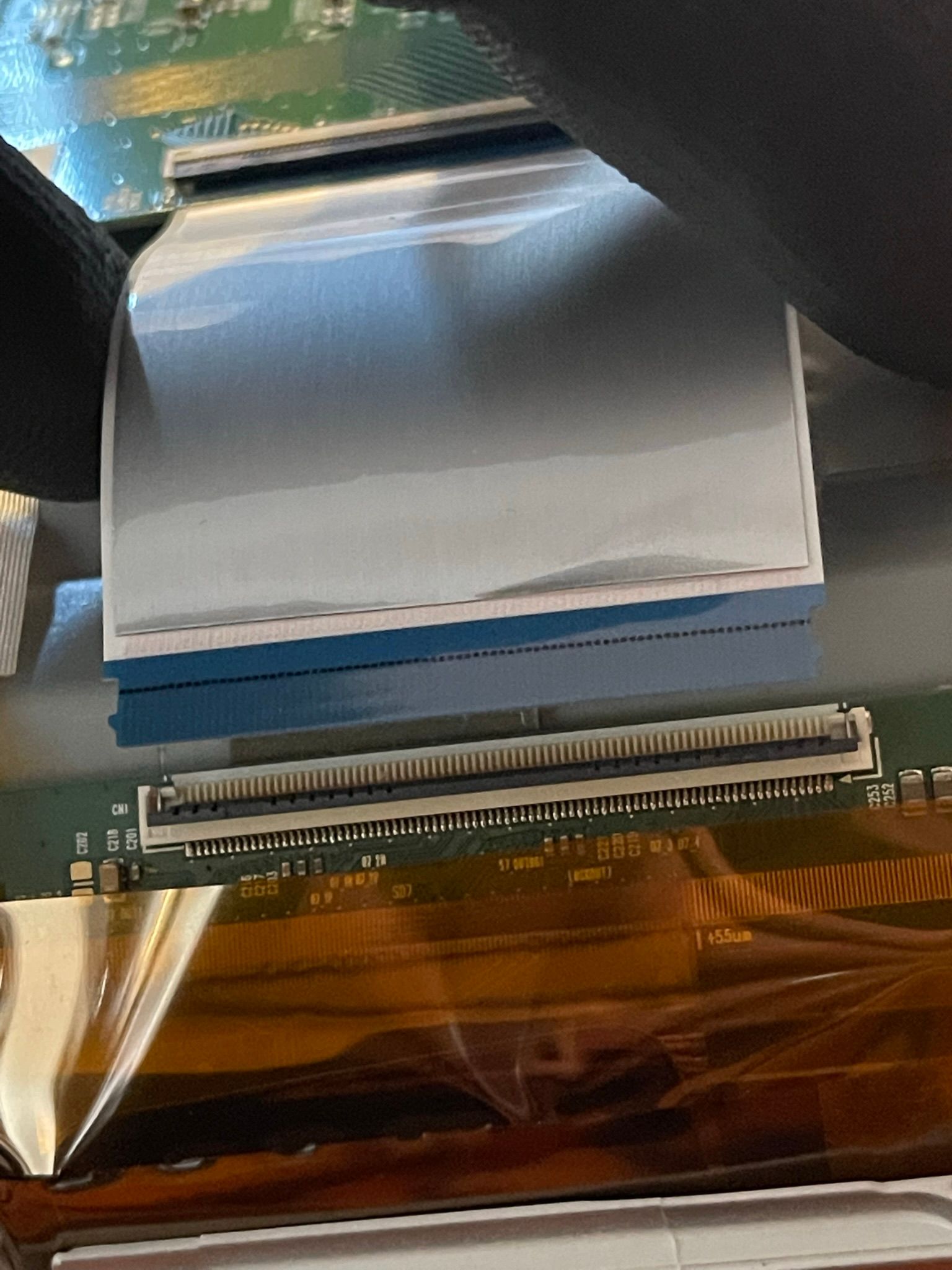
(You can also completely disconnect the ribbons to give yourself more space later on.)
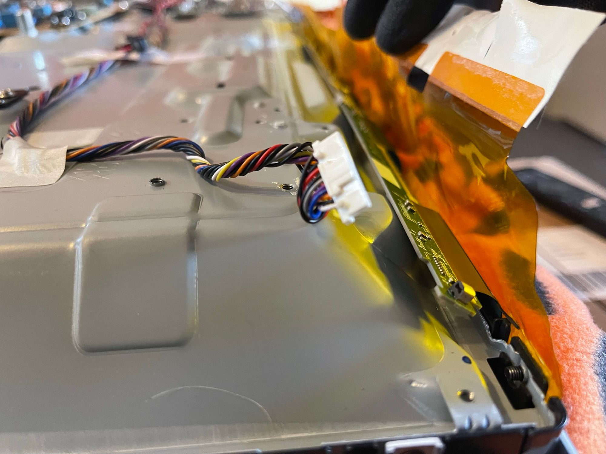
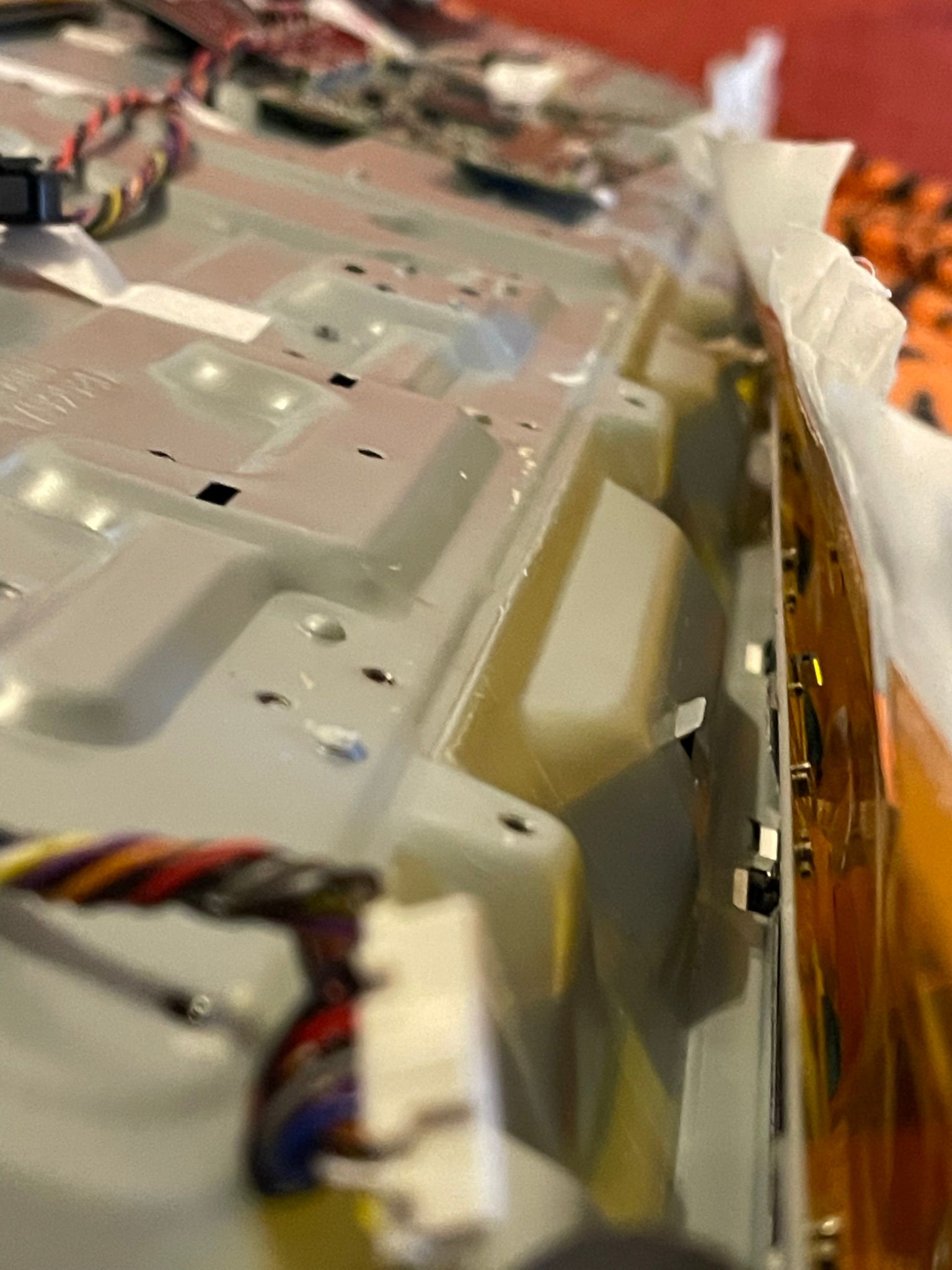
If you are lucky then you might not have the yellow protective film, if that's the case then you can skip this part.
Slowly lift the white tape without pulling on the yellow film. (use the yellow film to your advantage!)
If you want you can save time and cut the yellow film, but be careful not to damage anything...
Now gently pull back the yellow film and try not to damage any of the ribbon cables underneath it.
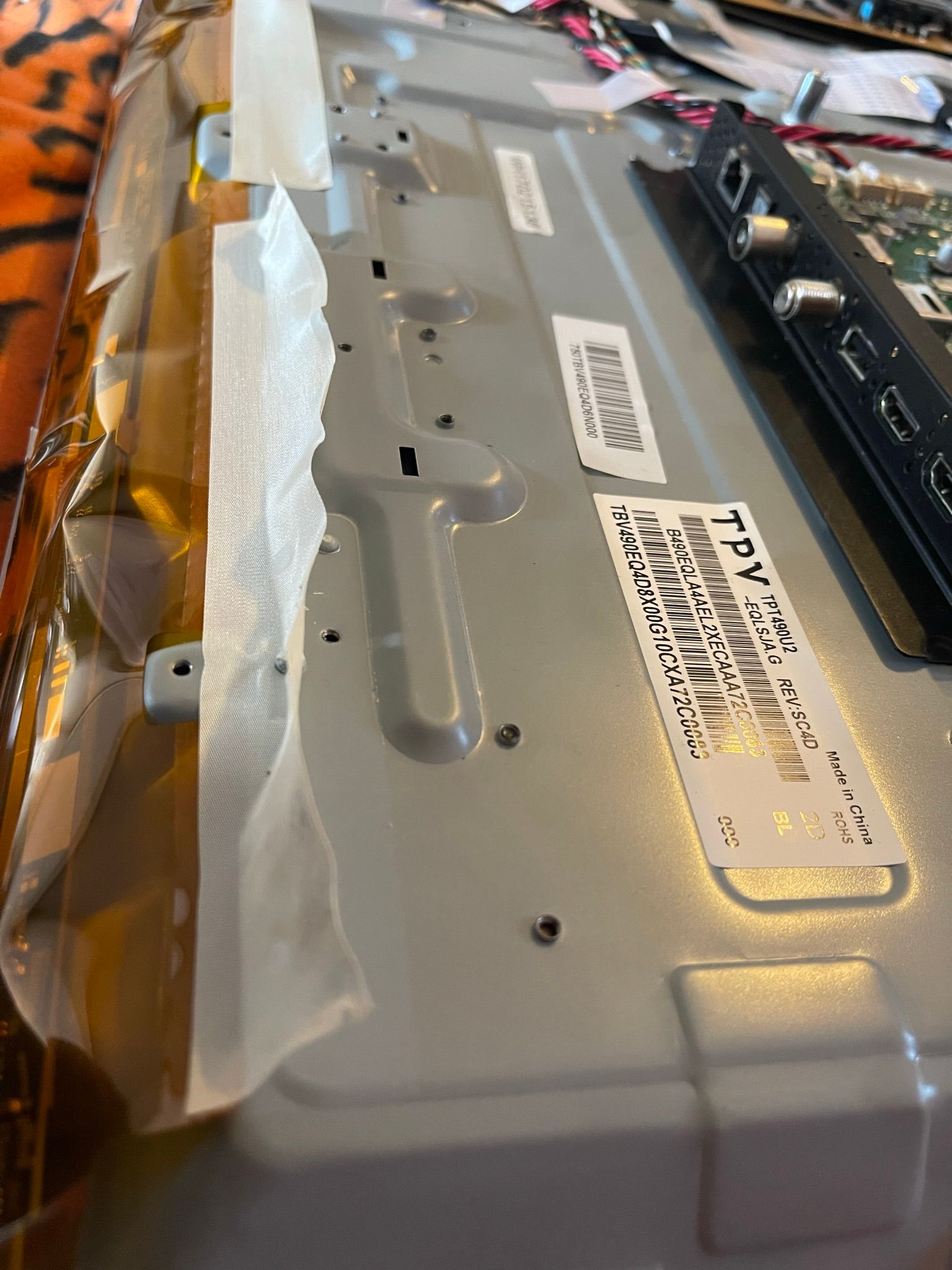
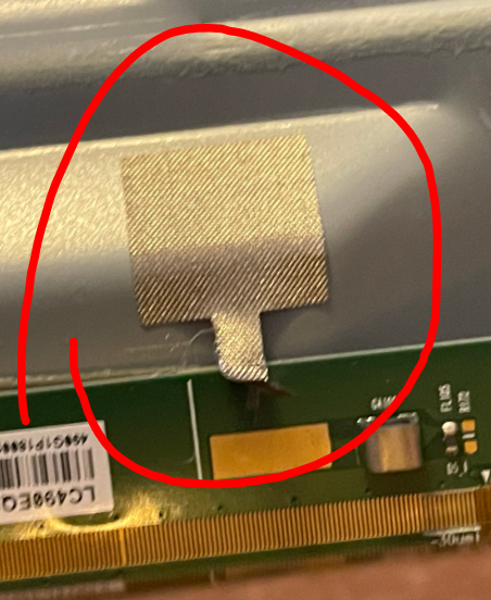
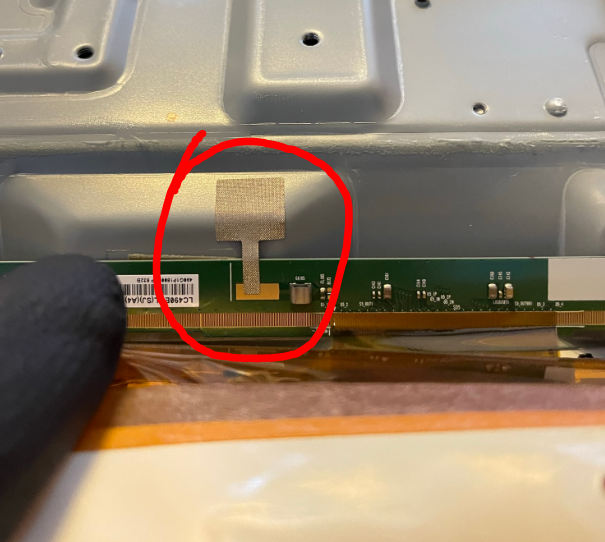
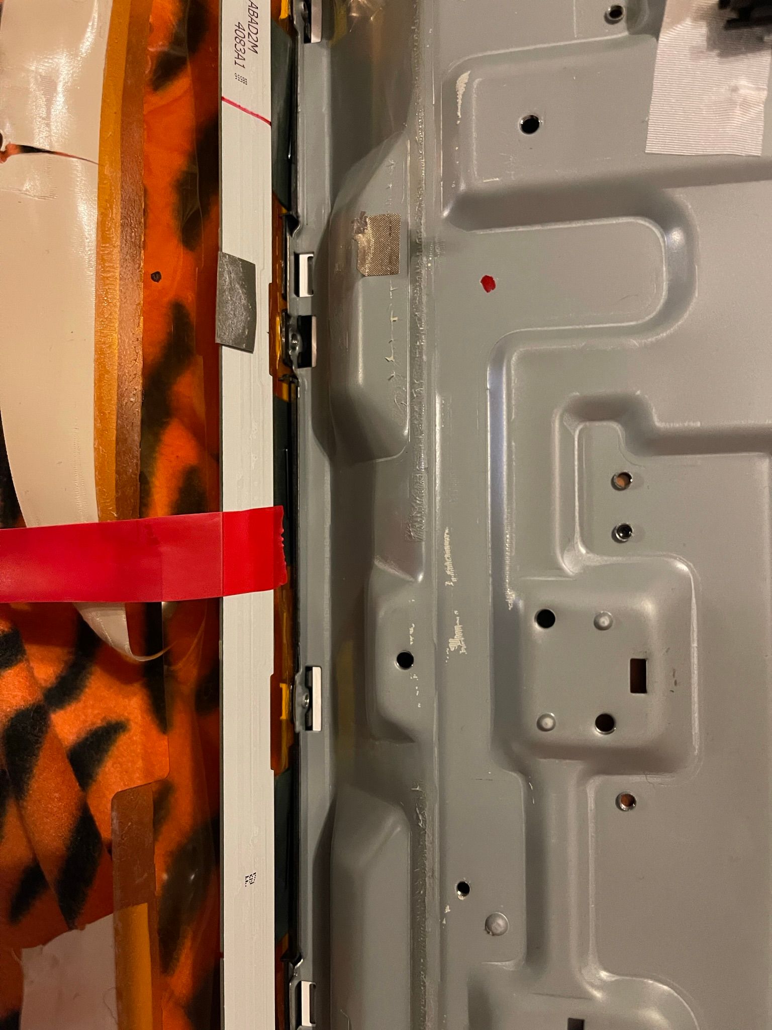
Then remove the tapes that hold the circuit breakout board to the frame
Now slowly remove the circuit board from the frame, I recommend cutting away the glue with a plastic tool to make sure you don't stress the board.
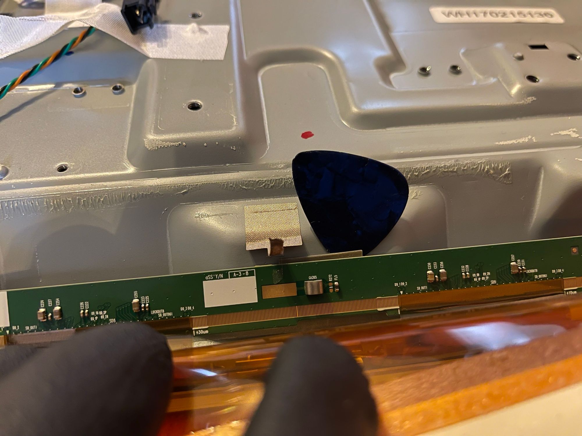
Make sure to take your time, it's not worth breaking it.
Now that the board is free we can start disassembling the LCD panel from the frame. We do this by splitting the frame and the lcd&diffueser assembly.
You have to remove the small black screws around the TV
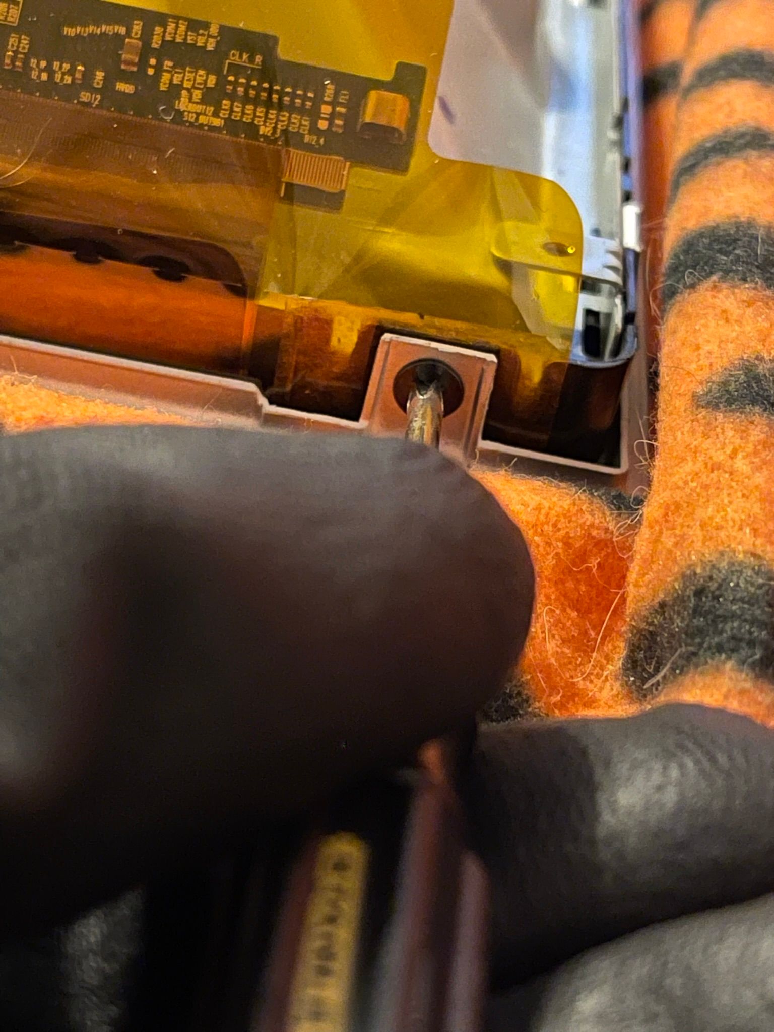
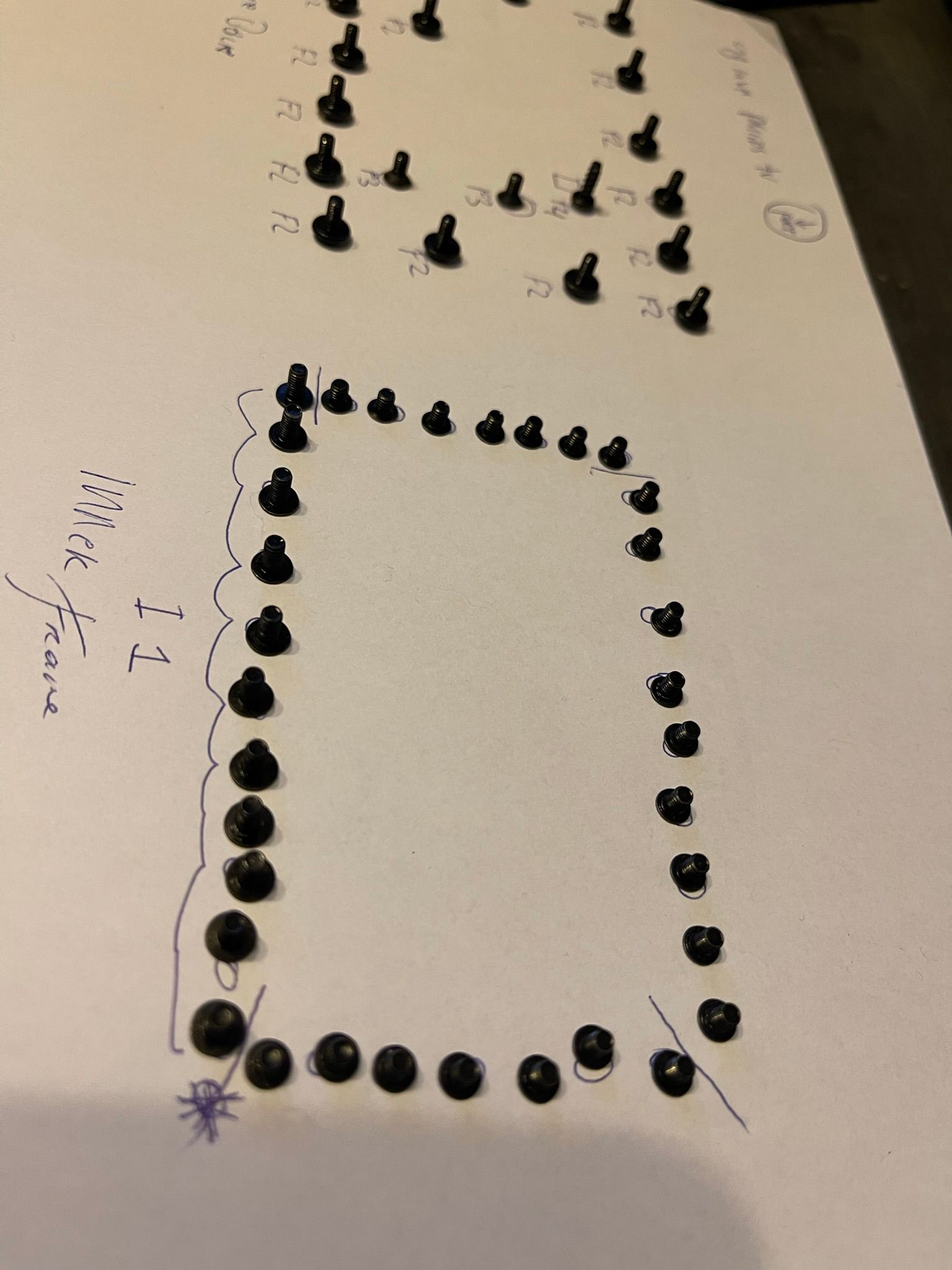
There are 11 screws at the bottom, 7 at both sides, and 9 at the top.
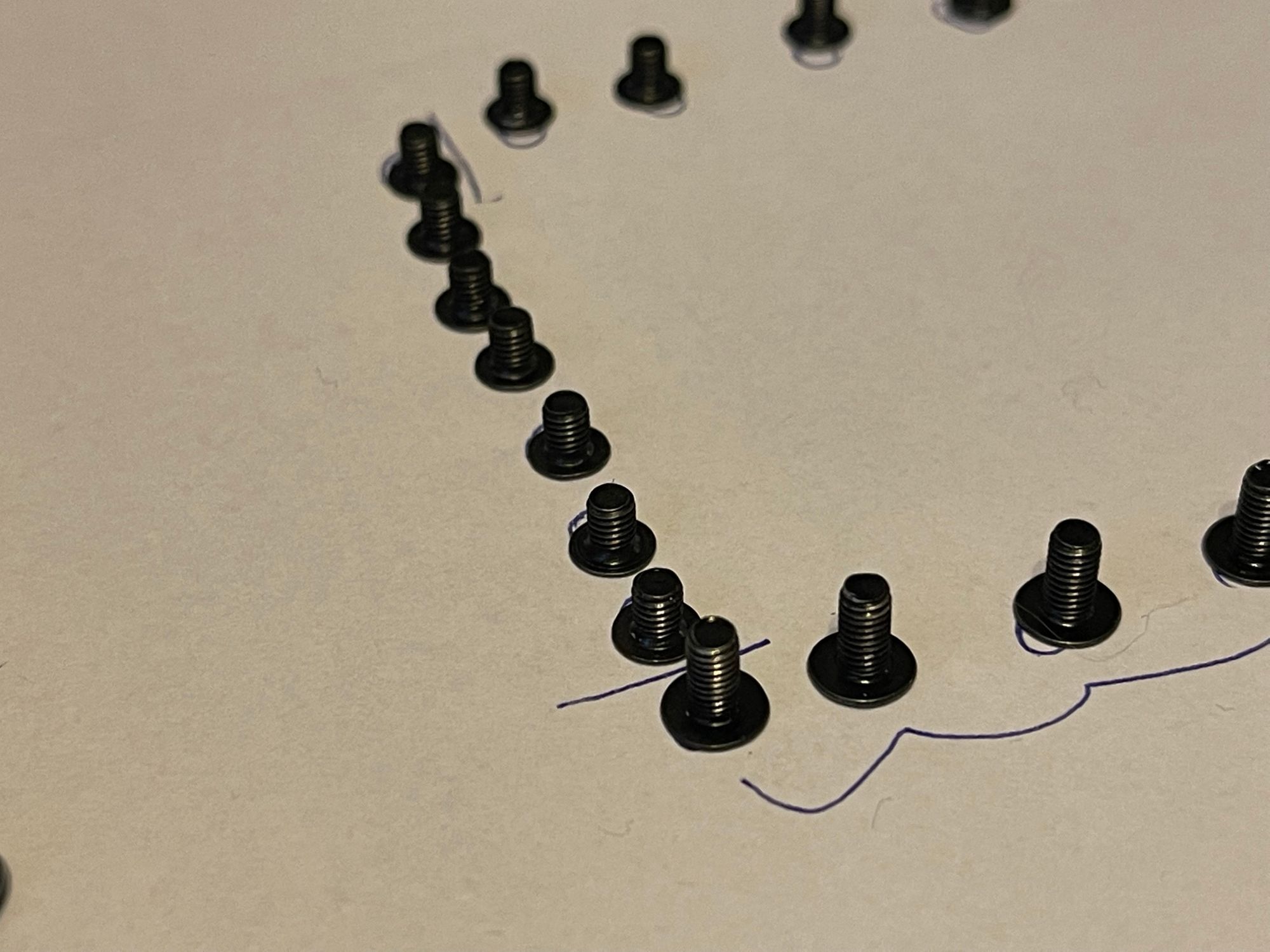
The screws at the bottom are bigger, keep them apart. That's why I use paper to organize my screws.
You now have to unclip the black plastic tabs that are all around the tv. (between the screws)
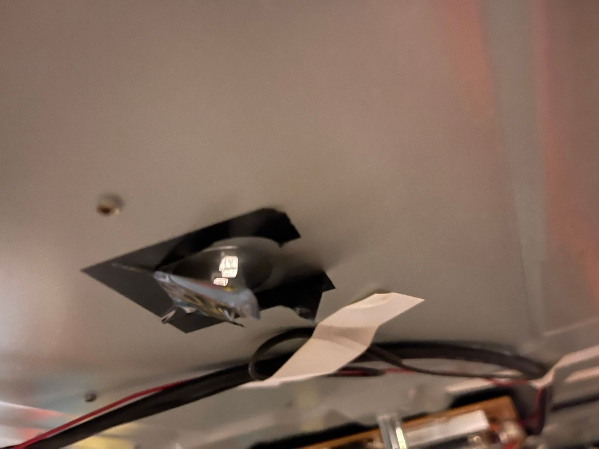
You can now pull up the frame, I used small pieces of rope and electrical tape to keep the circuit board from hanging onto the frame
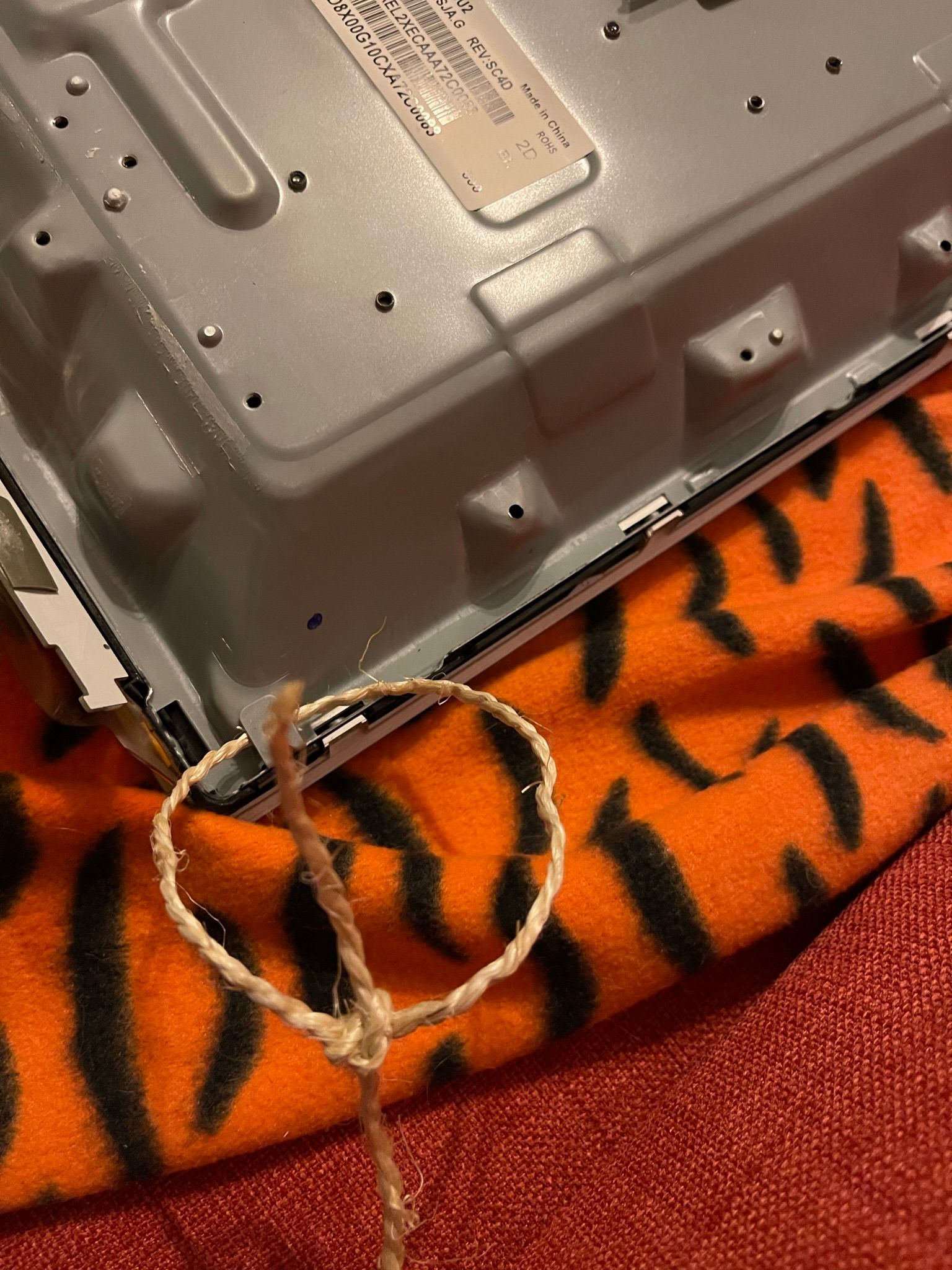
!!!WARNING!!! : For me, the bracket broke off while lifting the TV. So beware where you pick it up from!
Take your time, and it's easier with 2 people.
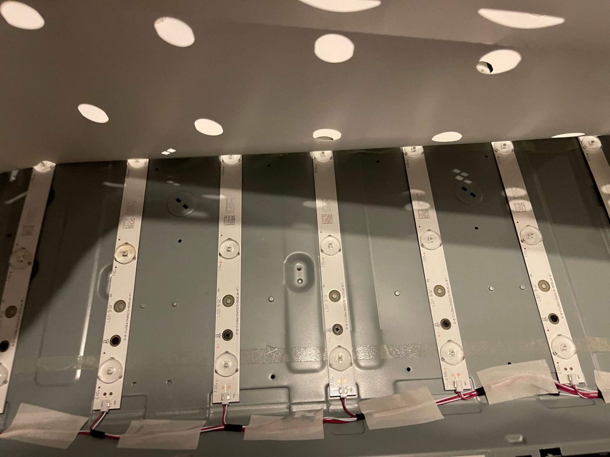
You should now have 2 parts. The led assembly (frame) and the glass/LCD/Diffuser assembly
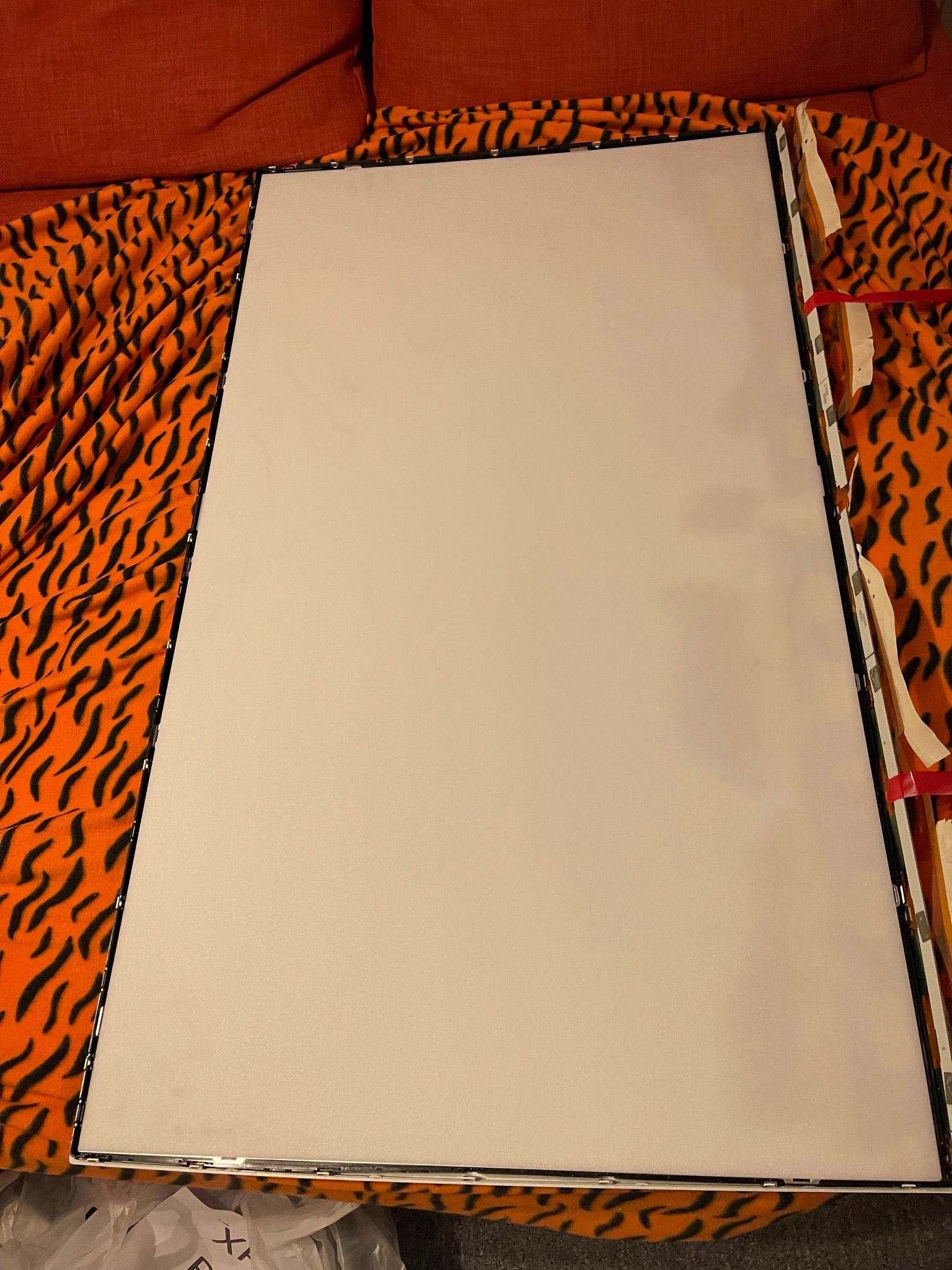
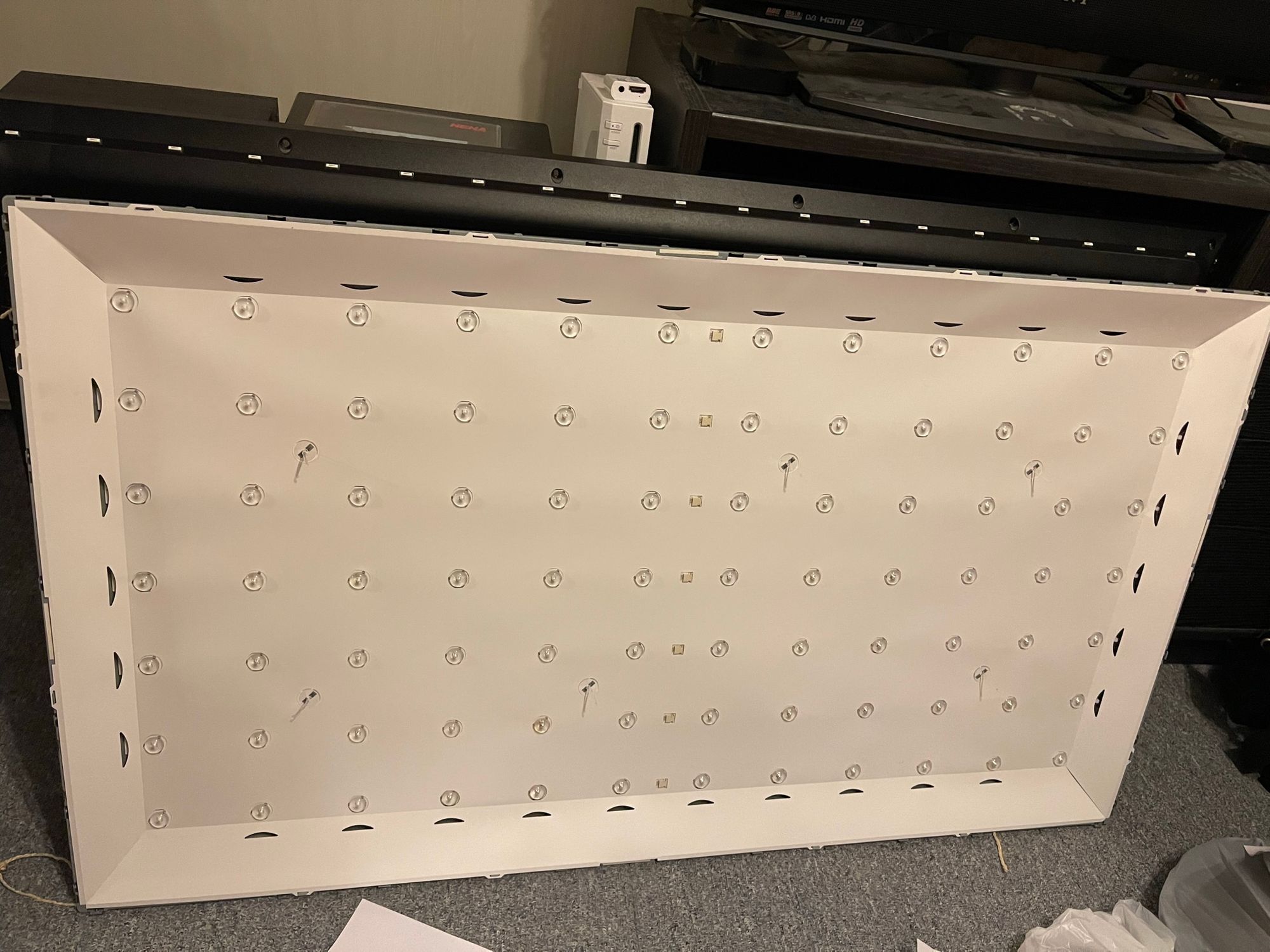
I covered the LCD assembly with a plastic cover to prevent dust and/or parts from entering.
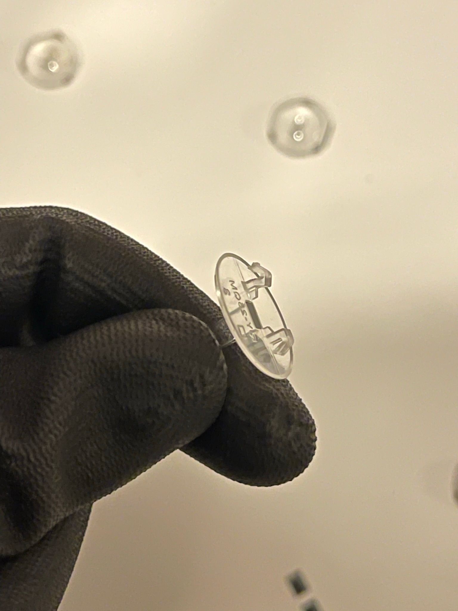
We can now remove the cover between the backlight LEDs, but first, we have to remove the support stands. 6 in total.
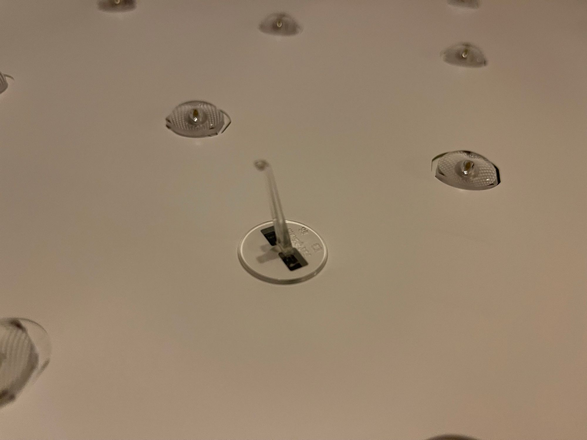
The official way would be to unclip them from the bottom, but I chose the dangerous quick, and dirty way of clipping them out from the top. Hereby bending the feet which could cause them to break. I just didn't feel like removing all the circuit boards just for these clips.
Worst case scenario? Glue :).
After removing all the stands you can now remove the paper.
Testing & Ordering parts:
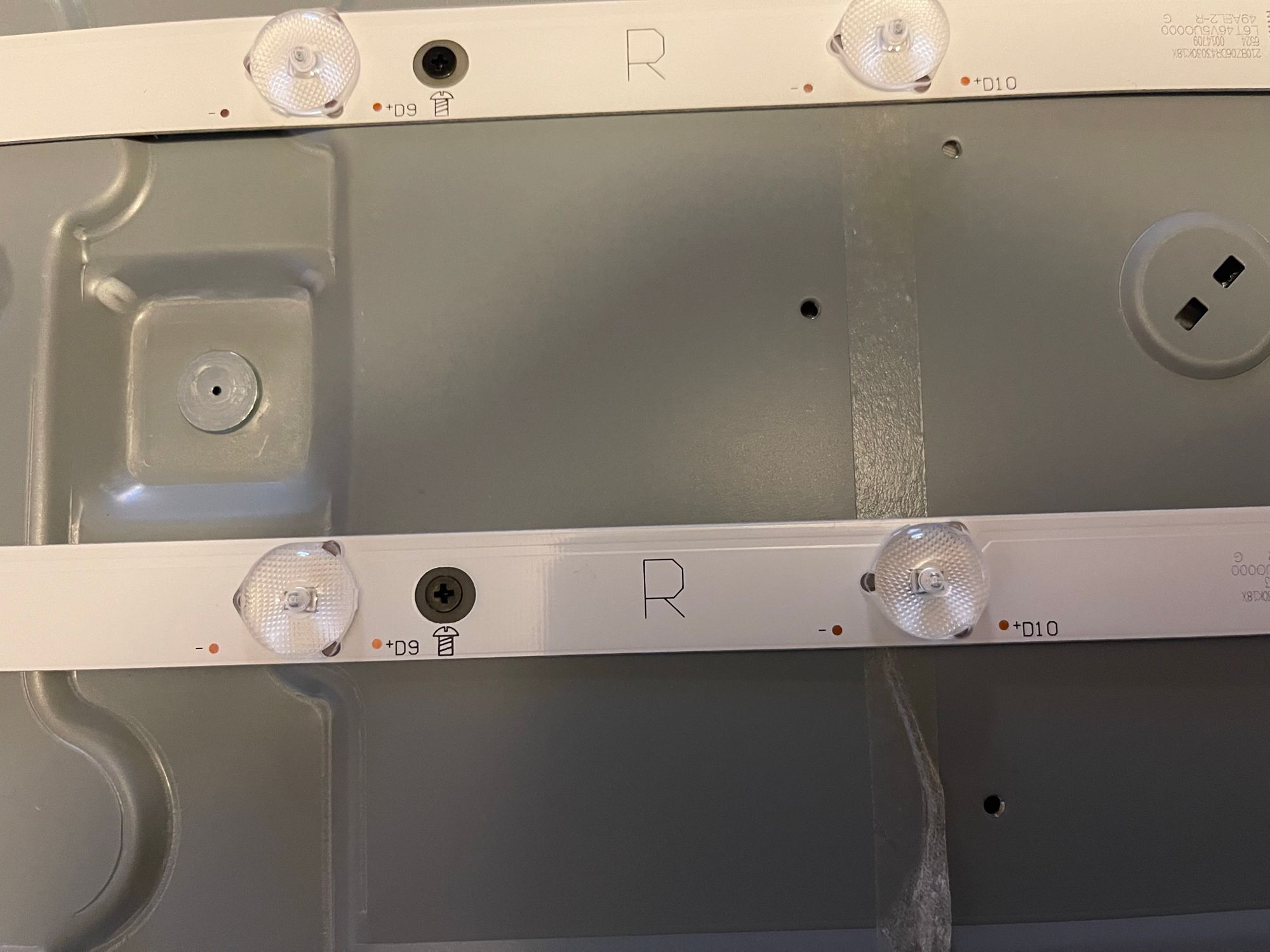
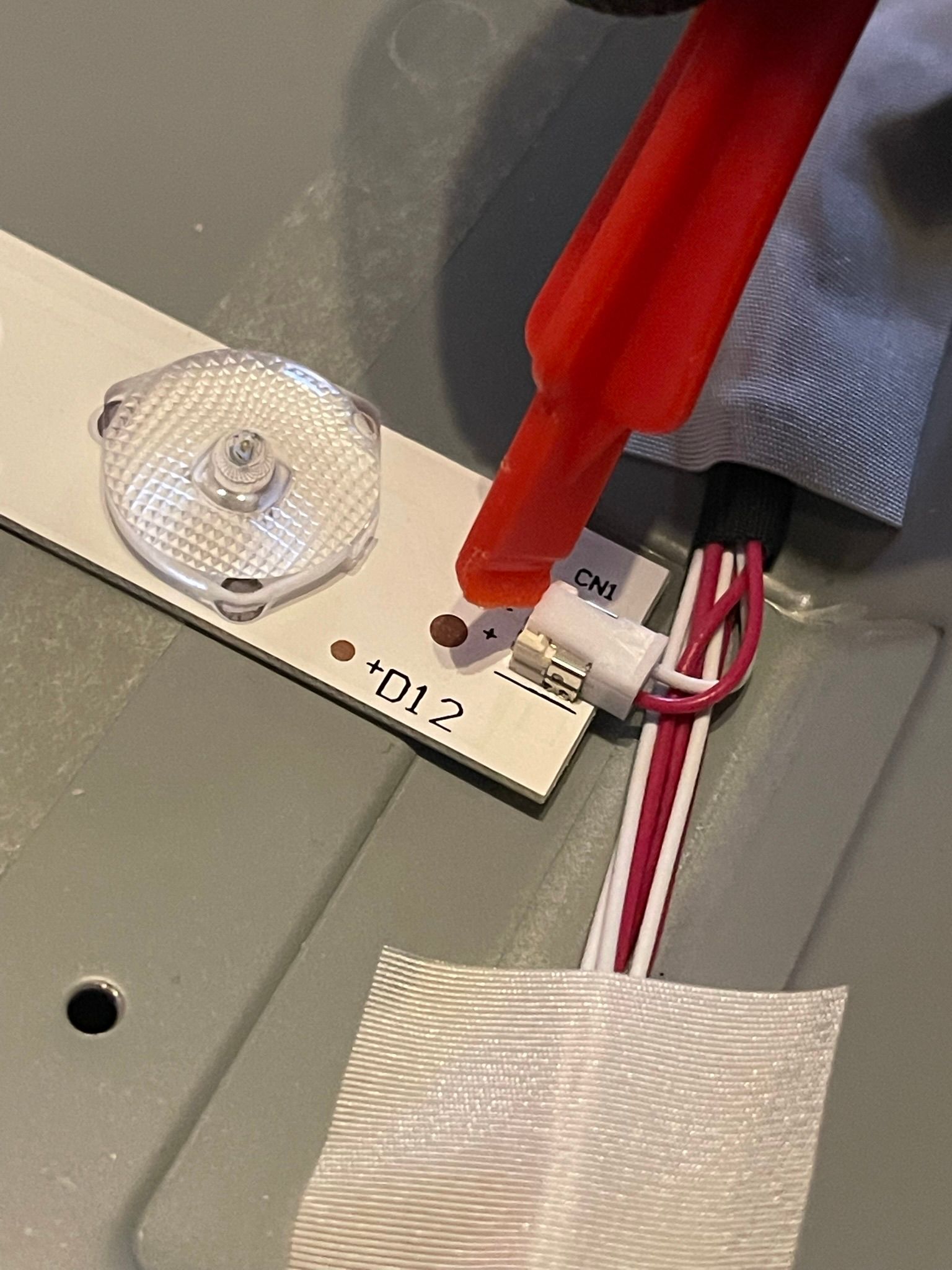
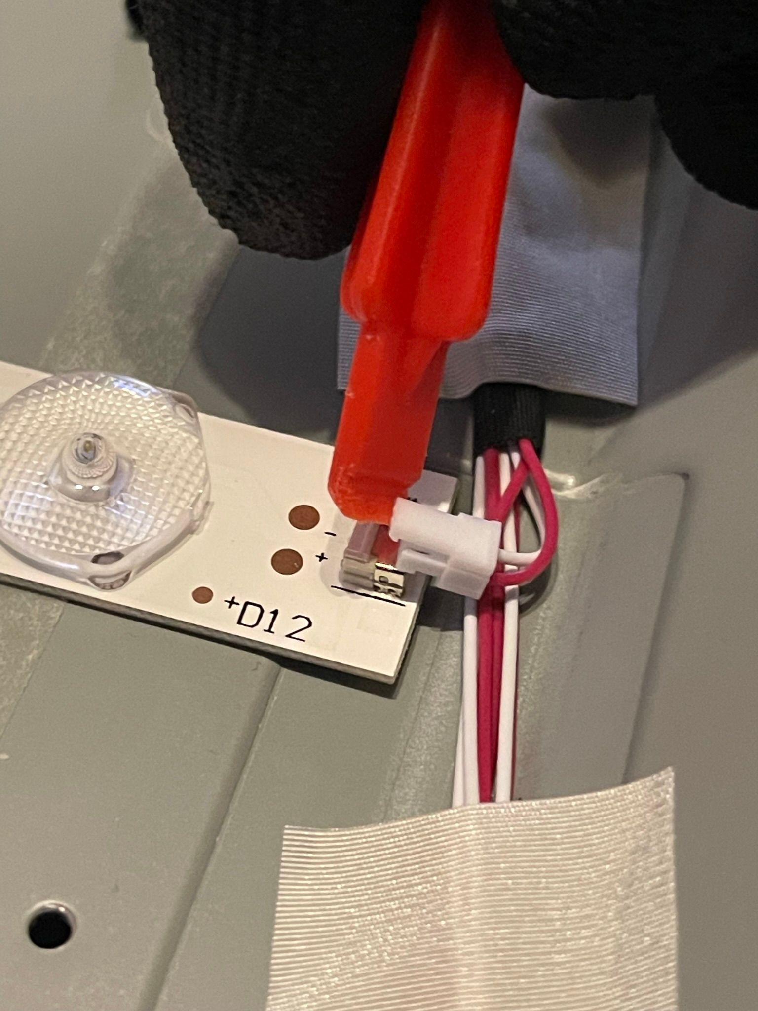
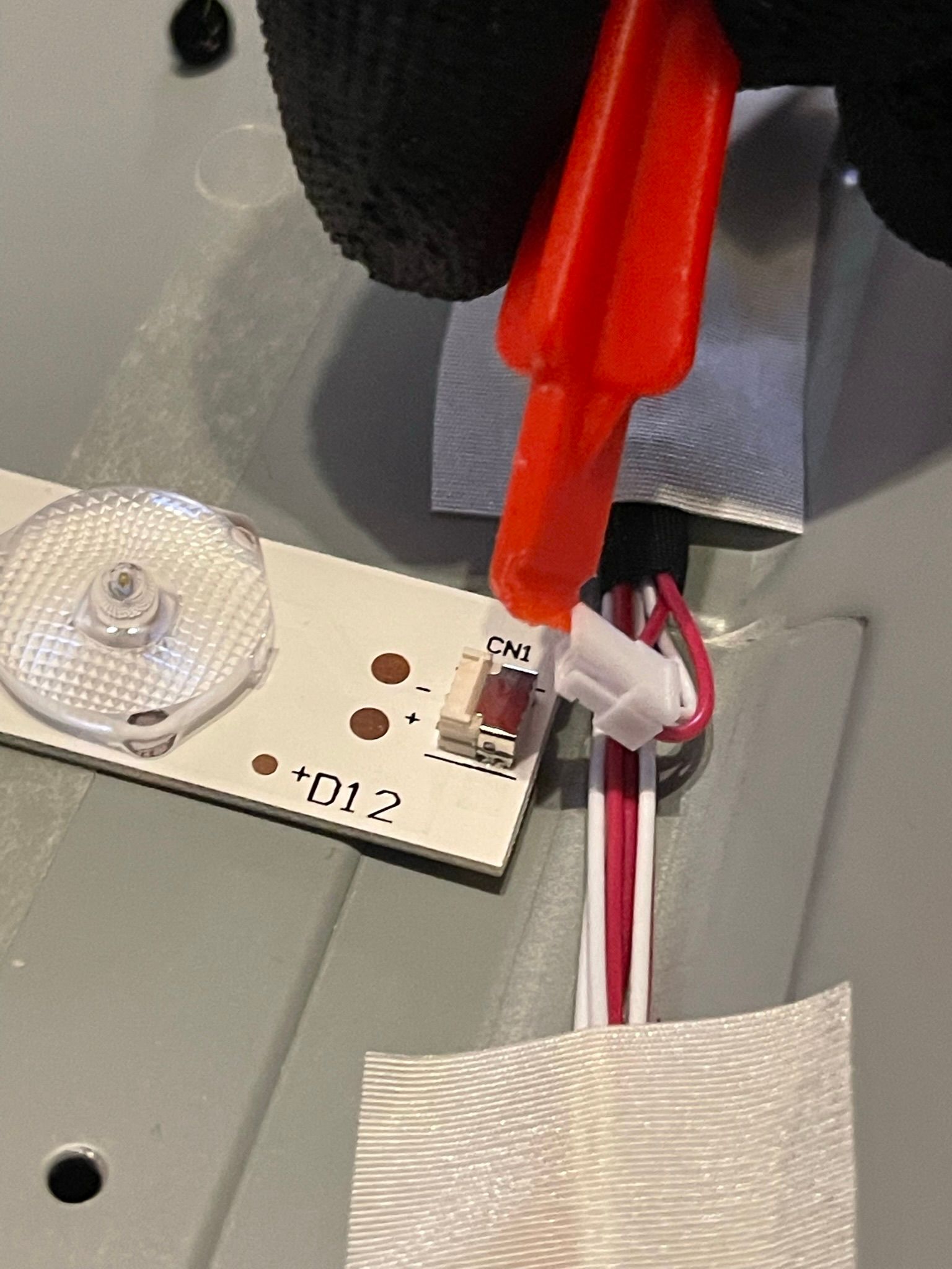
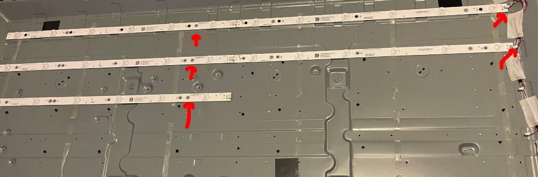
Now we can test the LEDs on the backlight by sending a small voltage through them. Luckily they added test points to the strips.
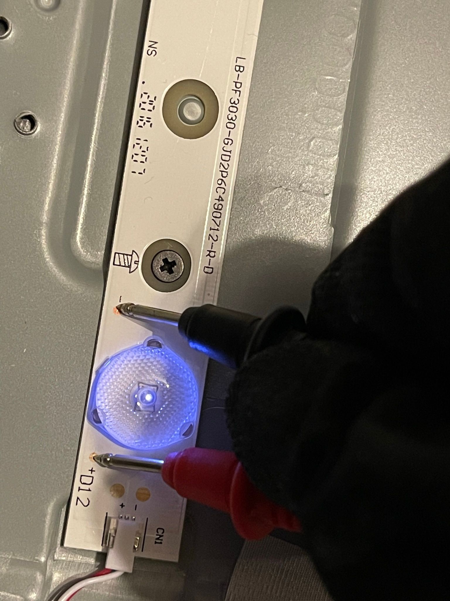
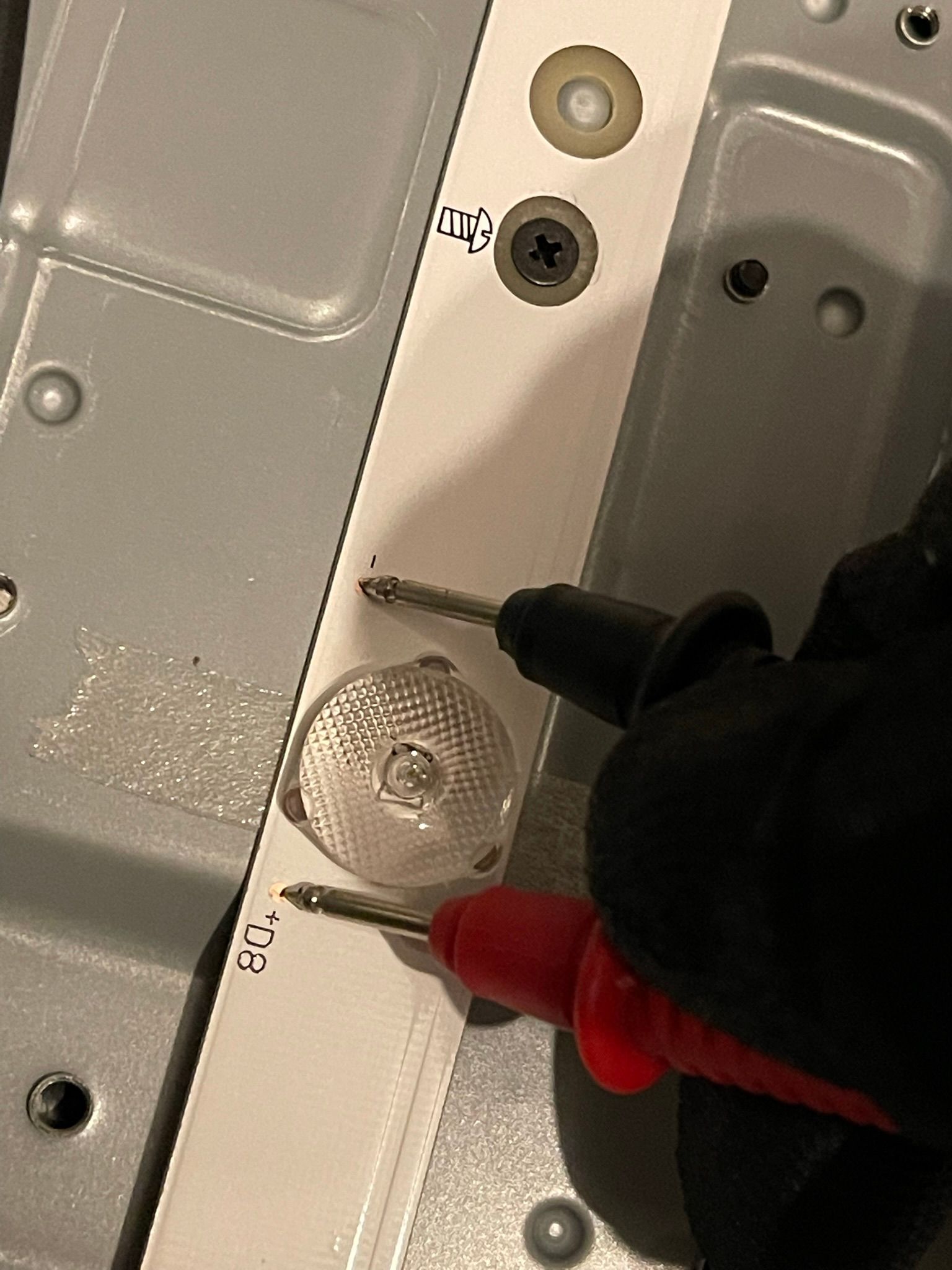
Quite a few were defect. So even if the LEDs weren't the issue, it would still be worth buying new ones while we are at it.
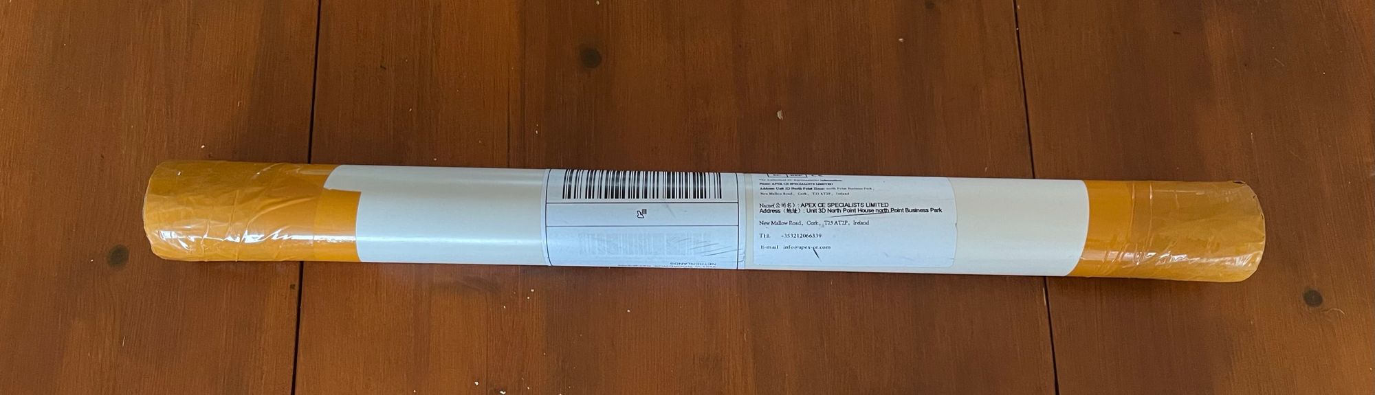
So i ordered the new leds from ebay for 30 euros

----------------------- +-15 days later -------------------------
The led strips arrived earlier then expected! That's always a nice surprise.
So we will start removing the old backlight strips:
Simply unscrew, disconnect, and pull them up from the glue-tape.
Now you place all the new ledstrips and connect them
Make sure to put them in the guiding holes and screw them back in place.
You can now reassemble the TV, Take your time and make sure to read backwords if you get stuck ;)
You should test it half-way but frankly i didnt care, either it works or i would part it out.
And then..:
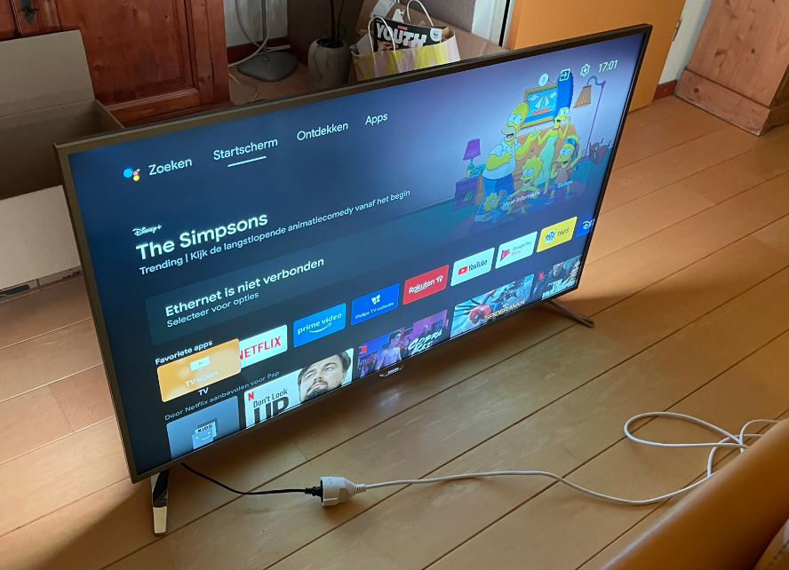
Epi Voilà! ;)
I did notice that there is some backlight bleeding and the quality is a little less, but you can't get a new 4k TV voor 30 euros :).